+8615674993216
 sales@forever-steels.com
 English
 العربية

Hydrostatic test pressure is one of the most frequently misunderstood figures in a steel-pipe RFQ. A mill hydrotest recorded for an individual pipe is not automatically the design pressure of a pipeline. A piping-system hydrotest is not automatically the maximum allowable working pressure. A flange Class is not a pressure in psi, and a PN marking is not a universal substitute for an ASME Class. These values come from different rules, apply to different parts of the delivery and can be limited by different components. Treating them as one “pressure rating” is how an apparently compliant pipe package becomes difficult to assemble or unsafe to test.
When the application is line pipe, begin by confirming the applicable API 5L line-pipe requirements and the project design basis before asking a supplier to quote a hydrotest value.
|
Term |
What it describes |
What the buyer must verify |
|
Mill hydrostatic test pressure |
A production test performed on pipe to the applicable product standard or purchaser requirement. |
Standard edition, grade, OD, wall, permitted stress basis, duration, gauge record and identification of each tested pipe or lot. |
|
Design pressure |
The pressure used by the responsible engineer for system design under the applicable code and operating envelope. |
Design code, temperature, corrosion allowance, load cases, medium, route and all connected components. |
|
MAWP / allowable pressure |
A calculated limit for a defined item or system under stated conditions. |
Who owns the calculation, temperature basis, material properties, weld/joint assumptions and limiting component. |
|
Flange or valve pressure-temperature rating |
A component rating determined by its governing standard, material group, temperature and configuration. |
Class or PN system, material, temperature derating, facing, bore, gasket, bolts and manufacturer data. |
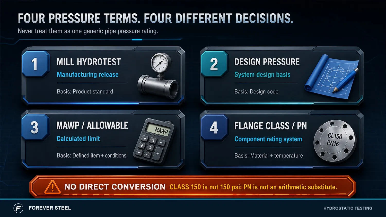
Figure 1. Mill hydrotest, design pressure, MAWP and flange Class/PN answer different questions.
The useful first question is therefore not “What pressure can this pipe take?” It is “Which pressure is being requested, for which defined item, at which temperature, under which code and with which connected components?” A steel pipe’s wall may pass a mill hydrotest, while a temporary blind, valve, flange gasket, instrument or flange material becomes the limiting component of a field test. Conversely, a Class-marked flange can be mechanically compatible with the pipe diameter but unsuitable at the design temperature or for the selected facing and gasket.
A mill hydrotest is a manufacturing release activity. It demonstrates leak tightness and compliance with the relevant product-standard requirement for the supplied pipe, subject to that standard’s scope. It is part of a product dossier alongside chemical and mechanical tests, NDT, dimensional inspection, marking and traceability. It does not validate the design, construction quality or test procedure of the completed pipeline or process piping system.
A system hydrotest is performed after a defined test boundary has been assembled. The system designer or construction specification establishes the test pressure, isolation points, temporary test equipment, medium, venting, gauge range and calibration, safety controls, hold duration, inspection method and records. A completed line may include fittings, bends, branch connections, valves, flanges, instruments and temporary blinds that were not present in the pipe mill. The test package must therefore be checked as a package, not inferred from a single pipe certificate.
There is no valid one-line pressure rating for “a 12 inch steel pipe.” Pressure capacity depends on OD, actual wall thickness, material grade and allowable stress, temperature, corrosion allowance, manufacturing route where relevant, weld/joint assumptions, design code, external loads and service conditions. A nominal Schedule label is a dimensional series, not a complete pressure rating. Two pipes with the same nominal size can have different internal capacity because their walls, grade, temperature basis and allowances differ.
For a quotation, state the physical definition first: OD x nominal wall x length; product standard and edition; grade; manufacturing route if controlled; ends; and inspection requirements. Then state the project design data separately. The supplier can confirm whether its offered product meets the stated product standard and requested manufacturing tests. The responsible engineer must confirm the pipe’s use within the complete system design. This division of responsibility avoids a supplier “rating” being mistaken for a code calculation.
ASME flange classes are pressure-temperature rating classes, not direct working-pressure labels. The applicable rating changes with material group and temperature; the flange standard also addresses dimensions, tolerances, marking and related requirements. PN designations likewise operate within their own standard and product family. A PN value should not be treated as a direct numeric conversion to an ASME Class without checking the specified standard, material, temperature and mating components.
For a flanged test boundary, confirm the selected Flanges against pipe size, bore/schedule, facing, gasket and bolting requirements before the test pressure is released.
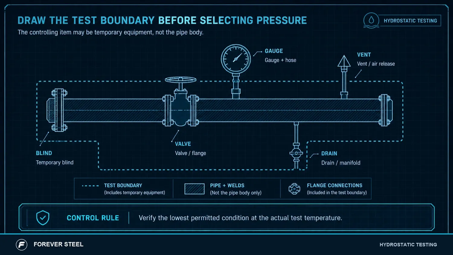
Figure 2. Draw the complete test boundary and identify the limiting item before approving pressure.
Every test boundary should be reviewed for the component with the lowest allowable test condition. That review includes the pipe body but also end closures, test blinds, reducing spools, branch connections, valves, flanges, gaskets, bolting, hoses, manifolds, gauges, relief devices and temporary supports. It also considers temperature and elevation effects where relevant. A temporary test blind is not an administrative detail: it must be identified, rated for the test condition and controlled in the test pack.
|
Review point |
Question to close before test |
Record to retain |
|
Pipe and spool |
Do OD, wall, grade, end preparation and weld status match the approved isometric and material traceability? |
MTC cross-reference, weld map, spool/tally identification. |
|
Pressure boundary |
Which item is the lowest-rated component at the actual test temperature? |
Component list, flange/valve data, blind register and calculation/approval. |
|
Instrumentation |
Are gauges suitable in range, calibrated and located to reveal the relevant pressure? |
Calibration certificates, gauge identification and test sketch. |
|
Test medium and venting |
Can the system be filled, vented and drained without trapping air or damaging the service condition? |
Method statement, vent/drain list and dewatering/drying plan. |
|
Acceptance |
What is the pressure, stabilization/hold requirement, permitted leakage and visual inspection scope? |
Signed test record, pressure chart/log and punch-list closure. |
Both seamless and welded pipe can be hydrotested when required by the applicable product specification. The key difference is not a simplistic statement that one route “has a pressure rating” and the other does not. The governing standard, grade, dimensions, manufacturing route, weld quality controls, NDT, product specification level and project supplementary requirements define what evidence is required. For welded line pipe, the inspection of seam welds, weld ends, repairs and plate/strip quality can be as important to release as the hydrotest itself.
For route-specific QA, see Weld Seam Inspection for ERW, LSAW and SSAW Pipes and keep hydrotest records linked to the same pipe identification.
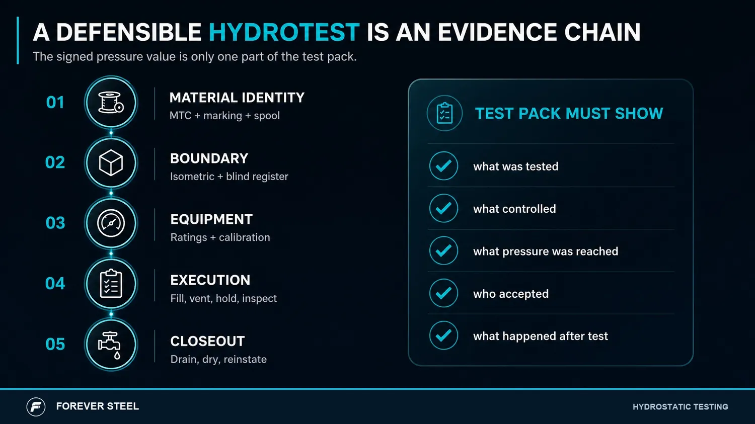
Figure 3. A defensible hydrotest record links material identity, boundary, equipment, execution and closeout.
A robust RFQ separates product testing from site/system testing. Under product testing, specify the product standard, hydrotest requirement, any purchaser-defined conditions permitted by the standard, NDT, test records, marking and MTC linkage. Under system testing, refer to the responsible project specification and make clear that final test pressure, boundaries and procedures are subject to engineered approval. This prevents bidders from silently pricing different obligations or promising a system result that is outside their manufacturing scope.
The ITP should state whether each pipe is tested, how the pressure is recorded, how gauges are calibrated, how failed tests are handled and how retests or repairs are controlled. For field work, add test-pack boundaries, valve status, temporary blinds, exclusion zones, venting, draining, water quality, preservation and reinstatement. Do not publish a universal pressure multiplier as a shortcut; codes and project conditions differ, and the lowest-rated component can control the permissible test condition.
Before selecting test pressure, draw the boundary. List every pipe segment, flange, valve, reducer, instrument, blind, hose, temporary manifold, vent and drain that will see pressure. The lowest permitted pressure-temperature condition of an included item can control the package. A high-capacity line pipe does not make an unsuitable temporary hose, gauge isolation valve or blind acceptable. Lowering the complete test pressure because one temporary item is weak may also fail the project objective. The responsible solution is usually to redesign the temporary equipment or split the package under approved engineering control.
The same boundary determines the test evidence. Mark limits on an isometric or test sketch, list component tags and material IDs, state the test medium and water-quality controls, and record the fill, vent, stabilization, hold, examination, depressurization, draining and reinstatement steps. Air trapped in a nominally hydrostatic system changes both safety and pressure behaviour, so controlled venting is not a paperwork detail. Site safety requirements, test procedure approval and competent supervision remain essential; an RFQ should never be treated as a field operating instruction.
A pipe’s pressure capability is not a timeless catalogue number. Temperature can affect allowable stress and flange or valve pressure-temperature ratings. Remaining wall, corrosion allowance, manufacturing tolerance, threading, bending, cyclic service, external pressure and service restrictions can matter. For existing plant piping, measured wall and damage mechanisms may be more relevant than the original MTC. Do not use a new-pipe product value as a fitness-for-service conclusion.
Class and PN markings cannot be converted by arithmetic. A Class 150 flange is a designation whose permitted condition depends on the governing ASME standard, material group and temperature, not a promise of 150 psi. PN is a nominal-pressure system under different standards. Confirm the exact flange standard, material, facing, bore, gasket, bolt set, nominal size and temperature with the responsible engineer before approving a test boundary. A mechanically fitting connection can still be unsuitable for the selected condition.
For mill testing, ask whether each length is tested or whether another permitted frequency applies; request the governing clause, pressure record, gauge traceability, failure/retest control and link to pipe marking. For a project system test, retain the signed test pack, boundary sketch, blind register, component rating review, gauge calibration, test chart or log, visual-examination record, punch closure and preservation/reinstatement record. These documents should share a controlled identifier with the spool or pipeline section. A test certificate that lacks the boundary and controlling items is difficult to defend during commissioning or a later investigation.
The RFQ can stay short: state product standard, grade, OD, wall, delivery condition, service and required manufacturing hydrotest evidence; separately reference the project design and system-test specification. For flanged assemblies, identify standard, class or PN, material, facing, gasket and bolting. At clarification, ask three questions: is the requested pressure a mill or system test, which document establishes it, and which item controls at test temperature? Those questions eliminate most late misunderstandings without asking the manufacturer to take responsibility for the project design.
When there is uncertainty, stop the commercial shorthand and request the governing reference. Confirm the product standard edition, the design code, the agreed test procedure and the component data sheet. This modest pause is normally faster than resolving an invalid test package after material, labour and temporary equipment have already been committed.
Phrases such as “pipe suitable for 1,000 psi” or “test to Class 300” are incomplete unless they identify the exact product, system, temperature, code basis and component boundary. They can cause sales, purchasing and site teams to believe that an engineering verification has occurred when it has not. Use the correct document for each decision: product standard and MTC for mill evidence; project code calculation for design/allowable pressure; approved test pack for the assembled hydrotest; and flange or valve standard for pressure-temperature compatibility.
A strong pressure-test file begins at material receipt. Link the pipe MTC and marking to the spool or line number, then connect weld maps, NDT records, flange and valve identification, gauge calibration and temporary-blind control to the same test package. At completion, retain the actual test pressure, start and finish time, temperature where required, stabilization/hold record, leakage observation, approved exceptions and drain/dry/preserve status. This creates a usable commissioning record rather than a single certificate with no clear relationship to the installed line.
This distinction matters when the pipe is delivered internationally. The manufacturer can normally provide product-standard evidence for the pipe it supplied. The EPC contractor or site team owns the assembled test boundary and field method; the responsible engineer owns code interpretation and final technical approval. The purchase order should respect those roles. Asking a pipe supplier for a final MAWP of an unknown completed system creates a misleading paper promise, while failing to request pipe-specific hydrotest and traceability evidence leaves the project without the manufacturing proof it actually needs.
Use hydrotest information as one part of an evidence chain, not as a standalone pressure certificate. First define the pipe under its product standard. Second define the system under its design code. Third identify the actual test boundary and limiting component. Finally make the documentation traceable from each pipe and weld through gauges, blinds and the signed test record. This approach protects both the mill release process and the project team from a costly but avoidable pressure-test mismatch.
1. API 5L PSL1 vs PSL2 for Oil and Gas Pipeline Projects
2. API 5CT Pre-Shipment Inspection: Thread Gauging, Drift Test, Hydrotest, NDT and Tally Check