+8615674993216
 sales@forever-steels.com
 English
 العربية

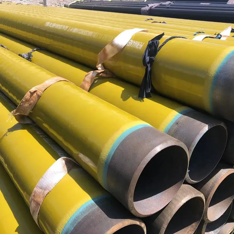
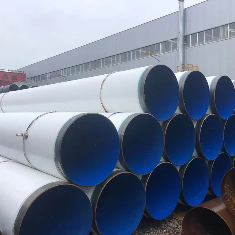
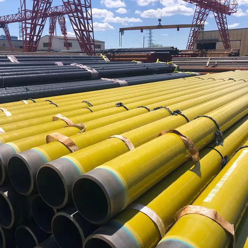
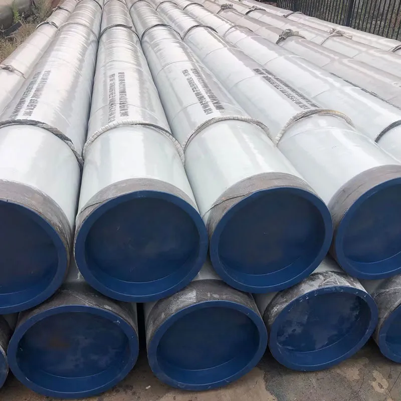
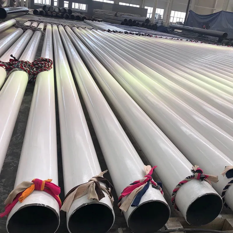
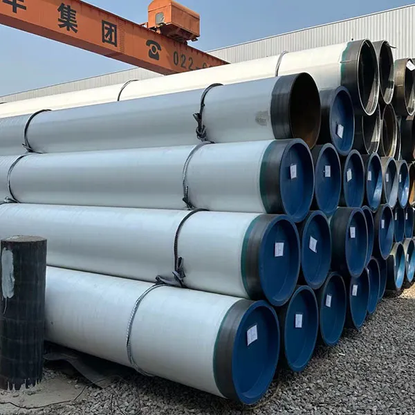
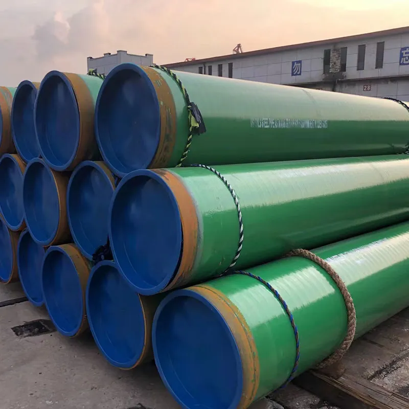
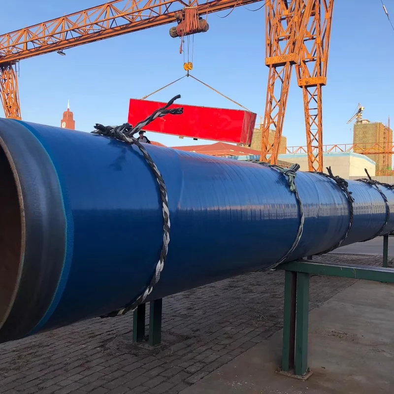
Fusion-bonded epoxy coated steel pipe is used where a factory-applied corrosion-protection layer is required for buried or submerged oil, gas and water pipelines. A complete quotation should define the base pipe, coating side, governing standard, service environment, design temperature, dry film thickness, pipe-end cutback, inspection requirements and release documentation.
Forever Steel supplies project-specific FBE coated steel pipe based on the approved material requisition and coating specification. Single-layer FBE and dual-layer FBE or abrasion-resistant overcoat systems may be considered according to installation and handling conditions. Final availability must be confirmed against pipe size, manufacturing route, coating system and order quantity.
| Supply item | Available range / specification |
|---|---|
| Base pipe | Standard, grade, PSL where applicable, manufacturing route and supplementary requirements |
| Dimensions | Outside diameter: 60.3–2540 mm. Wall thickness, length, quantity and dimensional tolerances to the order specification. |
| Coating location | External coating, internal lining or both |
| FBE system | Single-layer FBE, dual-layer FBE/ARO or FBE primer under a multilayer coating system |
| Governing standard | ISO 21809-2 for external single-layer FBE; CSA Z245.20 for plant-applied external FBE; AWWA C213 for FBE coatings and linings on steel water pipe and fittings. Specify the required edition and project amendments. |
| Service conditions | Conveyed medium, exposure, normal temperature and design temperature |
| Coating thickness | FBE dry film thickness (DFT): 200–600 μm (approximately 7.9–23.6 mils). The required nominal, minimum and maximum thickness depend on the specified coating system and governing standard; dual-layer / ARO layer thicknesses are specified separately. |
| Pipe ends | Bevel or plain end, cutback length, masked areas and field-joint interface |
| Inspection | Surface preparation, DFT, holiday detection, cure/adhesion and project tests |
| Documentation | MTC, coating records, repair log, traceability list, release and loading photographs |
Supply range: OD 60.3–2540 mm with FBE coating thickness of 200–600 μm (approximately 7.9–23.6 mils). Confirm the required size, coating location and system in the quotation. Thickness acceptance follows the governing standard and approved project specification. Conversion: 1 mil = 25.4 μm.
| Project condition | Possible coating route | Buyer should confirm |
|---|---|---|
| Buried oil or gas pipeline | External single-layer FBE | Standard, service temperature, cathodic-protection interface, DFT and holiday testing |
| Water transmission pipeline | FBE lining, external FBE or both | AWWA C213 scope, water-contact approval, fittings and special sections |
| HDD, road or river crossing | Dual-layer FBE or FBE with abrasion-resistant overcoat | Gouge resistance, handling method and field-joint system |
| Severe mechanical-damage exposure | Compare FBE/ARO with 3LPE or 3LPP | Backfill, installation method, impact risk, temperature and repair strategy |
FBE selection should be based on the full service and installation environment. A thicker coating alone does not automatically resolve abrasion, gouging, UV exposure, field-joint or cathodic-disbondment risks.
ISO 21809-2 covers plant-applied external single-layer FBE coatings for corrosion protection of bare steel pipe used in buried or submerged oil and gas pipeline transportation systems. The purchase order should identify the required edition and project-specific amendments.
AWWA C213 applies to fusion-bonded epoxy coatings and linings for steel water pipe, fittings and related components. Buyers should state whether the requirement covers the internal surface, external surface or both, and whether potable-water approval is required.
CSA Z245.20 is used for plant-applied external FBE coating on steel pipe. CSA Z245.21 should not be substituted automatically because it addresses plant-applied external polyethylene coating.
The project specification and approved coating-product data sheet should define service temperature, powder system, surface profile, application window, cure requirements, DFT, inspection frequency, repair limits and acceptance criteria. Any conflict between documents should be resolved before production.
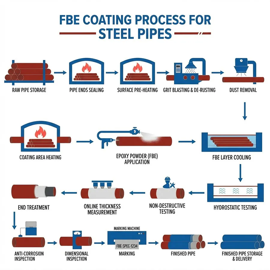
Final appearance alone cannot demonstrate FBE coating quality. The inspection package should follow the production sequence and remain traceable to the pipe, heat and coating batch.
| Inspection stage | Buyer evidence |
|---|---|
| Incoming pipe | MTC, heat-number traceability, dimensions, weld condition and end preparation |
| Surface preparation | Cleanliness record, anchor-profile readings, specified dust or salt checks, and environmental conditions |
| Coating material | Manufacturer, product designation, powder batch, shelf-life and storage record |
| Application and cure | Preheat and application parameters plus cure verification required by the governing specification |
| Film thickness | Calibrated DFT report with defined locations and minimum, average and maximum results |
| Coating continuity | Holiday-test method, voltage basis, equipment calibration, defect record and post-repair retest |
| Performance testing | Adhesion, cure, impact, bending, cathodic-disbondment or other tests required by the approved ITP |
| Repairs | Approved material, repair extent, preparation method, repair log and retest results |
| Pipe ends | Cutback dimensions, bevel condition, masking and end-protection photographs |
| Shipment release | Final report, traceability list, packing list, inspection release and loading photographs |
Third-party inspection, witness points and hold points should be agreed in the ITP before production.
Not automatically. The application side, conveyed medium, design temperature, approvals and governing standard must be stated separately.
State the governing standard, coating system, nominal and minimum DFT, permitted maximum where relevant, measurement locations and inspection frequency. Do not select thickness only from pipe diameter.
Where holiday detection is required, repaired areas should be retested using the approved method and voltage basis. Include repair and retest results in the final documentation.
It may be considered for HDD crossings, rocky terrain and installations with increased gouging or abrasion risk. Selection should follow the project installation assessment.
A typical dossier may include the base-pipe MTC, traceability list, coating-material records, surface-preparation report, DFT report, holiday-test report, production-test results, repair log, inspection release, packing list and loading photographs.
AWWA C213 FBE Water Pipe: RFQ and Inspection Guide