+8615674993216
 sales@forever-steels.com
 English
 العربية

An ERW pipe can meet its outside-diameter requirement and still obstruct an internal sleeve, coating tool or inspection device. For buyers who depend on a clear bore, ERW pipe internal weld bead acceptance needs three separate checks: the permitted seam profile, the remaining wall at the scarfed area and the passage required by the actual application. “Internal bead removed” is too incomplete to settle all three.
Specify the internal finish (internal weld bead removal or scarfing) when ordering ERW steel pipe, together with the pipe standard, dimensions and downstream operation. A functional bore requirement should be agreed before production, particularly when another component must travel through the full pipe length.
High-frequency welding (HFW) joins the formed strip edges of ERW pipe under pressure. The welding operation produces upset material at the seam; the internal projection is commonly called the inside weld bead or weld flash. Internal scarfing, also described as internal weld bead removal, removes that projection with a cutting tool inside the tube. Equipment manufacturers offer different internal scarfing systems and tooling sizes, so feasibility needs to be checked for the proposed bore and wall combination. Blissenbach’s tooling information explains this manufacturing operation.
Internal scarfing is a dimensional finishing operation. It does not establish weld bonding, heat-treatment compliance or pressure integrity. Those questions remain part of the product standard and inspection plan. For the metallurgical requirements, see ERW weld seam heat treatment and hardness record review.
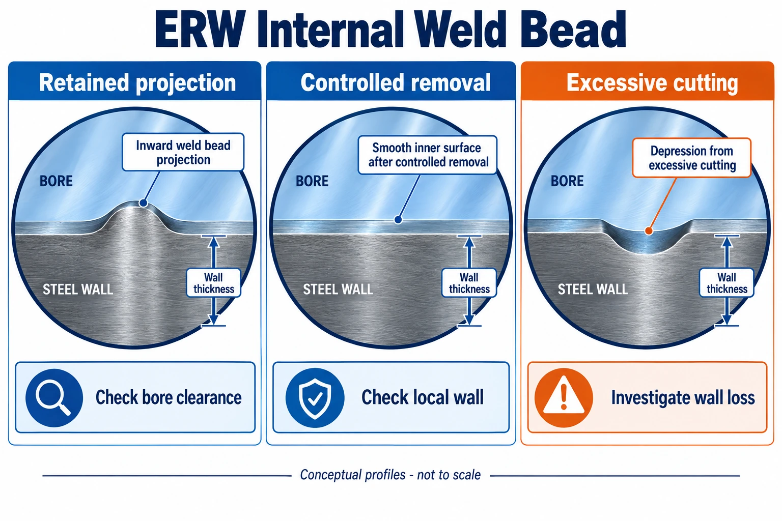
Figure 1. ERW pipe internal weld bead profiles are assessed against the adjacent bore surface. The sketches are schematic; they do not define an allowable bead height or cutting depth.
A buyer ordering pipe for ordinary fluid conveyance has a different acceptance problem from a fabricator inserting a close-fitting sleeve. The useful question is what the internal projection would interfere with, and which inspection can demonstrate that the interference has been controlled.
|
Downstream use |
Requirement to agree |
Evidence that answers the question |
|
Internal sleeve or inserted component |
Component envelope, insertion length and required clearance |
Agreed passage gauge or controlled trial assembly, with pipe identity |
|
Internal coating or lining |
Acceptable seam profile, sharp-edge condition and surface preparation |
Profile check and coating procedure review for the seam area |
|
Inspection tool or pig passage |
Tool envelope, bends/joints in the system and agreed bore envelope |
Defined full-length passage check where specified; review of system interfaces |
|
Drawing, bending or precision fabrication |
Internal finish and permitted local variation |
Process-specific trial or dimensional report agreed with the fabricator |
|
General pipe service without a special bore constraint |
Applicable product-standard and purchase-order requirements |
Required seam, dimensional and production-test records |
A short rigid plug passing through the pipe is evidence only for the agreed plug geometry. It does not prove that a longer sleeve, a flexible pig or a different inspection tool will behave identically. If function depends on a particular component, use its dimensions and operating constraints to define the test.
Do not infer the guaranteed clear bore from nominal OD minus twice nominal wall. Actual wall variation, ovality, straightness, the seam profile and any lining also affect the passage. The nominal calculation is a starting point for inquiry, not a release criterion.
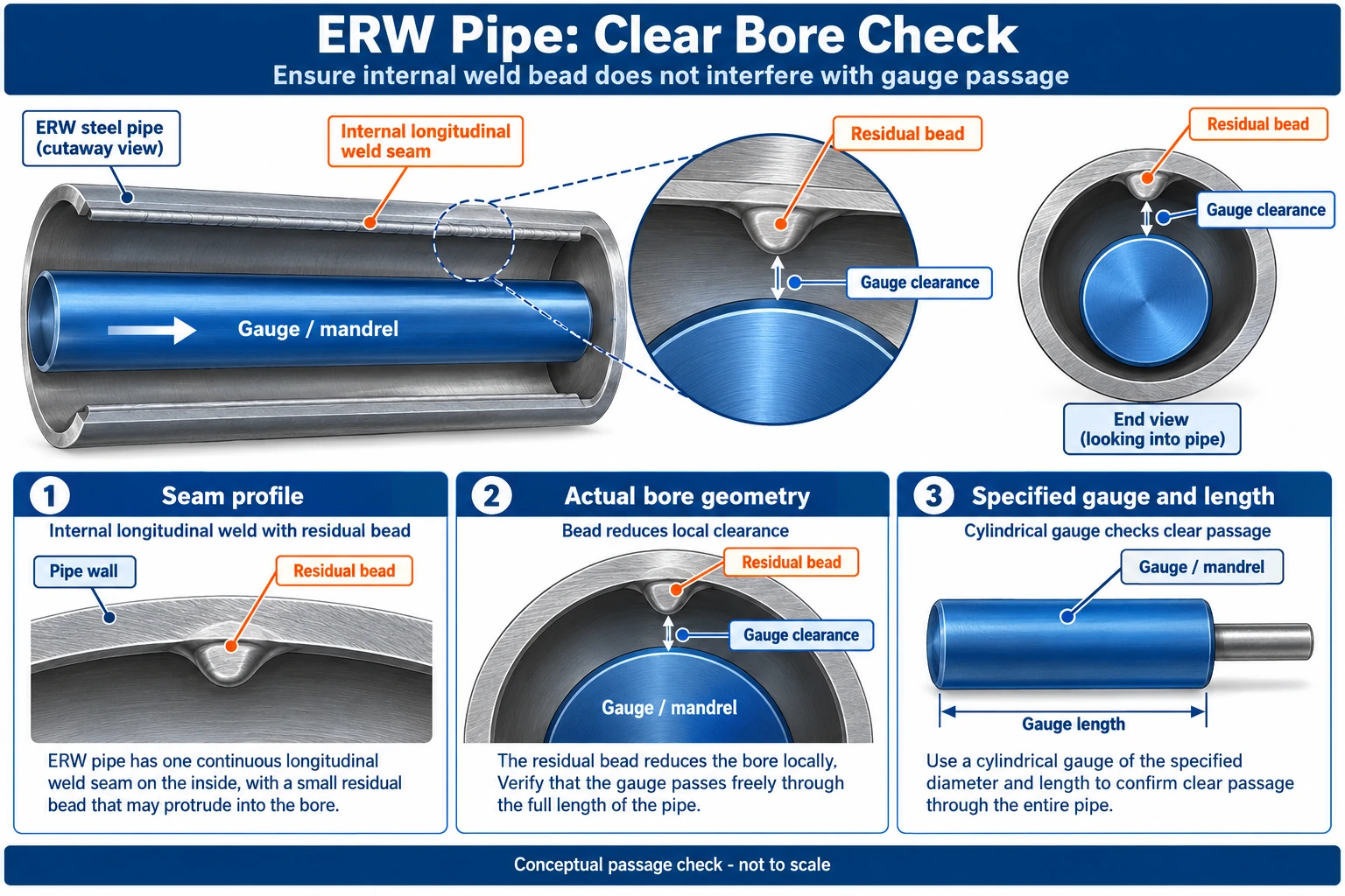
Figure 2. A conceptual passage check includes the inserted component and residual seam profile. The drawing is not to scale and does not define a clearance limit.
Residual internal weld bead height is the projection above the adjacent internal surface. A scarfing groove is a depression below that surface. A report should distinguish them rather than describing both as “seam height.” The measurement reference, instrument and accessible length should be agreed in the inspection and test plan, or ITP.
Removing more metal is not automatically better. If cutting enters the parent wall, the local remaining thickness needs to be checked against the applicable requirement. A smooth-looking groove can conceal a thickness problem; a visible residual projection can be acceptable if it meets the agreed profile and functional limits.
|
Inspection item |
What the report should identify |
Acceptance decision |
|
Residual projection |
Height relative to adjacent bore, position and measurement method |
Compare with the specified maximum |
|
Local depression |
Depth/profile and any associated surface imperfection |
Evaluate against the agreed seam finish and imperfection criteria |
|
Remaining wall |
Valid local thickness measurement at the affected area |
Confirm the applicable minimum wall requirement |
|
Clear passage |
Gauge diameter, length, shape, method and tested pipe length |
Confirm passage against the agreed functional envelope |
|
Loose scarfing material |
Bore inspection and cleaning result |
Remove debris before the required final inspection and shipment |
These are different measurements. A borescope image can locate a rough area or loose material, but an ordinary image without calibrated measurement cannot establish a precise bead height. A wall-thickness reading also needs a technique suitable for the local geometry.
Pipe-end inspection is convenient, but it does not represent every point along the seam. Tool condition or process interruptions can affect another section of the pipe. Nordinkraft describes scarfing monitoring that detects under-scarfing, over-scarfing and tool wear or breakage. That illustrates why a production record can add information that an end photograph lacks; it is not evidence that a particular supplier operates that system.
Agree how inaccessible length will be assessed. Depending on the requirement and available equipment, the plan may combine end measurements, internal viewing, production monitoring, selected section checks and a passage test. State sampling and coverage rather than treating a few photographs as a full-length dimensional survey.
When monitoring indicates a tool problem, the manufacturer should identify the affected production interval and the pipes made within it. Acceptance then follows the approved inspection and disposition procedure. Checking one later pipe does not resolve the earlier interval.
Buyers sometimes ask whether an ERW pipe becomes equivalent to seamless steel pipe once the inside weld bead is removed. It does not. The manufacturing route remains welded, and the required weld examination and production tests remain applicable.
Keep the seam-profile check alongside weld NDE, heat-treatment records and hydrostatic testing where required. None should be presented as a substitute for another. An acceptable passage gauge result confirms the agreed passage; it does not qualify weld metallurgy. Likewise, a successful hydrostatic test does not demonstrate a particular internal surface profile. For route-specific discontinuities and their investigation, see common weld defects, NDT and factory control; acceptable scarfing and bore clearance do not establish freedom from bond-line defects.
The governing standard should be settled first. ASTM A53 Type E, EN 10217-1 and API 5L HFW selection explains why these descriptions should not be used interchangeably when comparing offers.
Send the pipe standard and edition, grade, OD, wall basis, length and quantity. Then describe the operation that depends on the bore. Include an insertion drawing or tool envelope when available, any internal coating or lining, the permitted residual projection and the required remaining wall.
For acceptance, define the measurement reference, inspection coverage, passage-gauge geometry and record format. Ask the supplier to state any size-dependent limitation or departure in the quotation. A promise to “remove the bead” without these details leaves the acceptance method unresolved.
Compare quotations on supplied bore condition and inspection coverage. End viewing and a specified full-length passage check are different scopes.
Internal scarfing is a finishing operation in which a cutting tool inside the tube removes the inside weld bead, or weld flash, left by high-frequency welding. It addresses the internal seam profile and bore clearance; it does not replace weld examination, heat-treatment review or hydrostatic testing.
Do not assume it. The required internal finish depends on the product standard, order and manufacturing capability. If clearance or lining performance depends on removal, put that requirement in the inquiry and obtain a specific confirmation.
No. Scarfing removes weld upset material; it does not change the welded manufacturing route. Weld quality and the required production tests still need separate verification.
Use the applicable standard and the approved purchase requirement. There is no single project-independent figure for every ERW product and bore application. Specify the limit with its measurement reference and method.
Not necessarily. Nominal dimensions do not settle actual clear passage. Review the sleeve envelope against wall variation, ovality, seam profile and any lining, then agree the required passage or assembly check.
A borescope is useful for locating a condition. A precise dimensional acceptance requires a suitable calibrated measurement method. An unscaled photograph should not be used as a numerical height record.
Check the local remaining wall and surface condition. Follow the product-standard and approved nonconformance procedure for disposition. Grinding or accepting the area solely because it looks smooth does not resolve the thickness requirement.
· ERW Weld Seam Heat Treatment and Hardness Record Review
· ASTM A53 Type E vs EN 10217-1 vs API 5L HFW
· Weld Seam Inspection for ERW, LSAW and SSAW Pipes
· Common Weld Defects in Welded Steel Pipe: Causes, NDT and Factory Control
· Ernst Blissenbach — Internal Tube Scarfing Systems
· Tube Scarfing Equipment — Mechanical Internal Scarfing Tool Range