+8615674993216
 sales@forever-steels.com
 English
 العربية

Factory control of welded-pipe defects starts with a traceable indication, not a generic reject label. Identify the pipe and affected production interval, record the location and measured size, evaluate the finding against the governing acceptance criteria, and select an approved disposition. Then correct the process cause, complete required re-examination and close the release record. For visual definitions of cracks, porosity, inclusions and fusion defects, use the welding-defect identification guide.
A discontinuity becomes a defect only when it exceeds the applicable acceptance criteria. There is no single universal depth, length or pore-count limit for every welded pipe. Limits change with product standard, pipe route, grade, service, weld type, examination method and project supplements.
ISO 6520-1 provides a classification system for geometric imperfections in fusion welds, while ISO 5817 assigns quality levels for production workmanship in applicable fusion-welded joints. AWS inspection guidance makes the same practical distinction: an interruption in weld uniformity is an imperfection or discontinuity; it is rejectable only when the governing specification classifies its type, size, distribution or location as unacceptable.
This distinction matters in nonconformance reports. A useful record says, for example, 'intermittent undercut at the outside weld toe, 140 mm from Pipe End A, measured depth and length recorded,' rather than 'bad weld.' The first description can be compared with a clause and traced through repair and re-examination. The second cannot.
ERW/HFW steel pipe has a narrow longitudinal bond line produced by resistance heating and forging pressure. Process-specific concerns include cold weld or incomplete bonding, oxide inclusions, weld-line offset, hook-type cracking associated with strip-edge features, inadequate bead removal and incorrect seam heat treatment.
LSAW steel pipe and SSAW steel pipe use submerged-arc fusion welding with deposited weld metal. Their common concerns include lack of fusion, incomplete penetration, slag inclusion, porosity, undercut, cracks, excessive reinforcement and start/stop or repair-area discontinuities. LSAW has a longitudinal seam; SSAW has a helical seam, so scan geometry, pipe-end coverage and repair locations must be planned accordingly.
API Spec 5L establishes manufacturing, inspection, testing, marking and traceability requirements for seamless and welded line pipe. The 47th edition also places added attention on HFW pipe quality and NDE controls. For other products, ASTM, EN, ISO, AWWA or project-specific requirements may govern instead. The pipe designation on the purchase order must therefore drive the acceptance basis.
| Finding | Process checks to investigate | Record needed for disposition |
|---|---|---|
| Crack-like indication | Welding and heat-treatment history, restraint, consumables and any prior repair | Pipe/location map, measured indication, acceptance clause and approved disposition |
| Lack of fusion or penetration | Joint preparation, fit-up, heat input, travel speed and seam tracking | NDT location/extent, production interval and procedure review |
| Porosity or inclusion | Joint cleanliness, flux/consumable condition and process-appropriate shielding | Distribution and size, relevant process records and re-examination |
| Undercut or weld profile | Parameters, weld position, bead placement and local geometry | Measured depth/length/profile and applicable limit |
| HFW bond-line indication | Strip edges, heating, squeeze conditions and seam treatment | Line records, affected pipe population and qualified examination |
Cracks may occur in the weld metal, heat-affected zone or adjacent base metal. They can be longitudinal, transverse, crater-related, hydrogen-assisted or associated with a hard microstructure, excessive restraint or an unsuitable repair cycle. Because a crack is sharp and may propagate under pressure cycling, fatigue, impact or low temperature, it must not be hidden by grinding or an unapproved cosmetic weld pass.
· Contain and identify the affected pipe or production interval; preserve heat, coil/plate and pipe traceability.
· Confirm whether the indication is surface-breaking or subsurface using the specified VT, MT, PT, UT or RT technique.
· Review consumable condition, preheat/interpass control, heat input, restraint, seam heat treatment and any prior repair.
· Use only a repair route permitted by the product standard and approved procedure; re-examine the repaired area and affected zone.
Lack of fusion means the weld metal has not bonded to the base-metal sidewall or to a previous weld pass. Incomplete penetration means the required joint thickness has not been fused through the root. Both are planar discontinuities, but their causes and locations differ. Calling both 'not welded through' prevents useful root-cause analysis.
Common causes include incorrect joint preparation, insufficient heat input, high travel speed, unfavorable torch or electrode angle, poor bead placement, contaminated fusion faces, incorrect root gap or land, and inadequate back-gouging. In automated pipe mills, seam tracking, forming accuracy and parameter stability are equally important.
A recent Eng-Tips Welding Engineering discussion on GMAW short-circuit lack of fusion illustrates why field troubleshooting must begin with the actual joint, material thickness, transfer mode, shielding gas, qualified procedure and recorded parameters. Practitioner discussions can help frame an investigation, but the approved WPS/PQR and governing acceptance standard remain controlling.
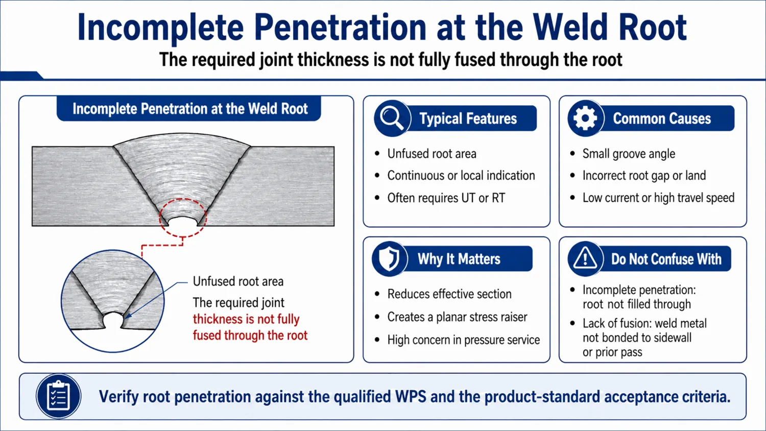
Figure 2. Incomplete penetration at the weld root and its distinction from lack of fusion.
Undercut is a groove melted into the base metal at the weld toe or root and left unfilled. It may be continuous or intermittent and may occur on the inside or outside surface. Typical process causes include excessive current, excessive travel speed, unfavorable electrode angle, arc blow or insufficient dwell and fill at the toe.
The risk is not simply appearance. Undercut reduces the local load-bearing section and sharpens the weld-to-base-metal transition. Its significance increases at fatigue-sensitive details, repaired zones, high-stress locations and thin-wall pipe. Record the exact location, measured depth and cumulative length, then compare those values with the governing criteria.
The worked examples in AWS Inspection Trends' review of common weld discontinuities reinforce an important factory distinction: identification and probable-cause analysis support process correction, while acceptance still comes from the applicable code or product specification.
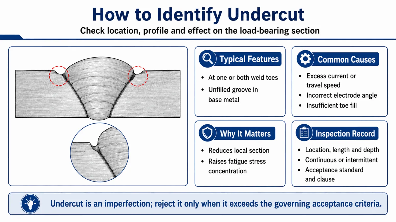
Figure 3. Undercut identification and inspection-record requirements.
Porosity forms when gas is trapped as the weld pool solidifies. It may be isolated, clustered, aligned or elongated. Surface pores may be found visually, but internal porosity normally requires volumetric examination. A few rounded indications and a dense cluster do not carry the same implication, so count, size, distribution and location must be recorded.
Frequent causes include oil, rust, moisture, paint or scale on the joint; damp flux or consumables; inadequate shielding-gas flow; leaks or drafts; excessive arc length; unstable parameters; and contaminated strip or plate edges. Corrective action should restore the process condition, not merely cover the visible pore.
For terminology context, an American Welding Society Forum technical discussion distinguishes a single gas pore from a distribution described as porosity. This is useful shop-floor context, while formal classification and acceptance must still follow the specified standard and inspection procedure.
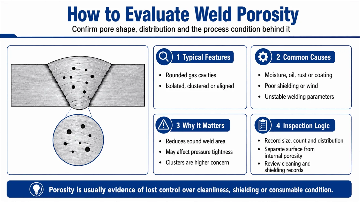
Figure 4. Porosity shape, distribution, causes and inspection logic.
Slag inclusion is most relevant to flux-using fusion processes and multipass welding. Slag or flux residue may become trapped between passes, at the sidewall or near an unfavorable bead profile. In ERW/HFW pipe, the analogous process concern is often oxide inclusion along the bond line rather than slag from a consumable flux.
For submerged-arc welding, verify flux condition and recovery, groove cleanliness, interpass cleaning where applicable, bead placement, heat input and travel speed. For HFW, review strip-edge preparation, squeeze pressure, heat input, weld-line monitoring, bead trimming and heat-treatment records. UT or RT selection must match the expected indication orientation and the applicable product standard.
For additional manufacturing context, Oil & Gas Journal's technical review of ERW seam characteristics and defects describes cold-weld zones, process misalignment and hook-crack mechanisms in older ERW line pipe. These legacy examples should not be generalized to modern HFW production, but they show why seam terminology, material history and manufacturing route matter.
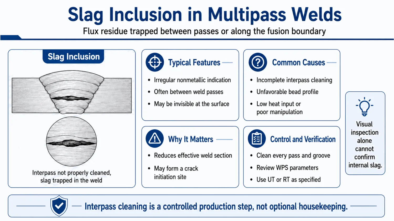
Figure 5. Slag inclusion in a multipass fusion weld.
Overlap, underfill, root concavity, excessive reinforcement, burn-through, misalignment, spatter, arc strikes and poor start/stop profiles can often be screened by visual and dimensional inspection. They should still be described precisely because they do not have the same mechanism or acceptance rule.
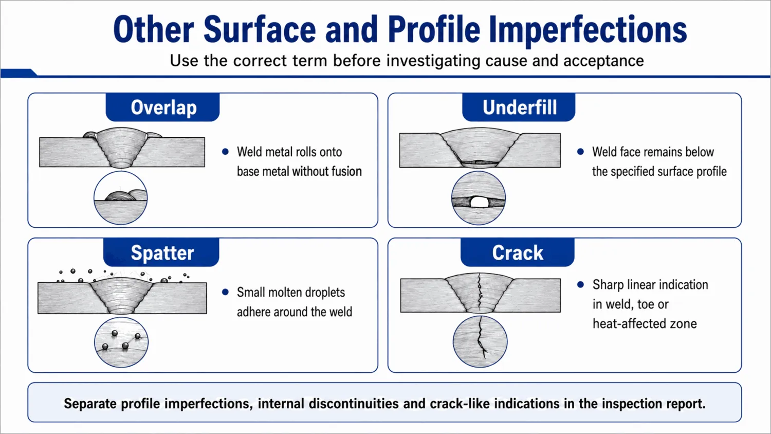
Figure 6. Examples of overlap, underfill, spatter and cracking.
· Overlap indicates weld metal lying on the base metal without proper fusion at the edge.
· Underfill or excessive concavity reduces the weld section below the required profile.
· Burn-through is local melt-through and requires evaluation of remaining wall and repair permission.
· Misalignment or weld-line offset affects load transfer, wall profile and sometimes NDT signal interpretation.
· Arc strikes outside the weld can create localized hard zones or cracking; mark and evaluate them under the applicable procedure.
ISO 17635 states that method selection should consider quality requirements, material, weld thickness, welding process and examination extent. Acceptance levels are related to, but are not a direct one-to-one translation of, ISO 5817 quality levels. This is why a report stating only '100% NDT passed' is incomplete.
Industry inspection literature also shows why the expected defect family must be defined before selecting or interpreting an inspection system; see the Pipeline Technology Journal overview of ERW and SAW pipe defects in inline inspection. Its operational perspective supplements, but does not replace, the applicable manufacturing standard and qualified NDT procedure.
|
Method |
Useful for |
Important limitation |
|
VT |
Weld profile, undercut, overlap, visible cracks, arc strikes, surface pores, dimensions |
Surface and line-of-sight only; requires adequate cleaning, lighting and access |
|
PT |
Fine surface-breaking cracks and pores on suitable nonporous materials |
Only indications open to the examined surface |
|
MT |
Surface and near-surface crack-like indications in ferromagnetic steel |
Not suitable for nonmagnetic grades; magnetization direction matters |
|
UT/AUT |
Lack of fusion, incomplete penetration, cracks and other reflectors when beam orientation is suitable |
Calibration, scan plan, geometry, dead zones and operator/system setup matter |
|
RT/DR |
Porosity, many inclusions and density/profile changes |
Tight planar indications may be difficult when orientation is unfavorable |
|
ET/EM |
Selected weld-zone or surface discontinuities in applicable tube/pipe routes |
Technique and reference standards must match product and dimensions |
|
Hydrotest |
Pressure-boundary leakage or gross weakness during the specified test |
Does not classify or prove absence of every weld discontinuity |
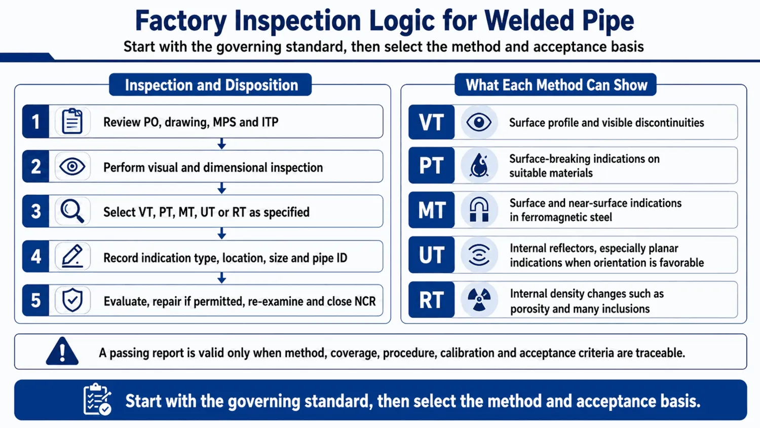
Figure 7. Factory inspection and disposition logic for welded pipe.
The purchase order, product standard, grade, PSL or class, service supplements, pipe dimensions, weld route, NDT method and coverage, acceptance level, repair permission, re-examination scope and documentation format should be aligned in the manufacturing procedure specification (MPS) and inspection and test plan (ITP). A late request for different acceptance criteria can change equipment, cycle time and yield.
Fusion-welded production should operate to qualified WPS/PQR requirements where applicable. Control joint preparation, fit-up, consumables, flux or shielding gas, heat input, travel speed, wire/electrode position, preheat/interpass temperature and seam tracking. ERW/HFW production additionally requires controlled edge presentation, heating, squeeze/forge conditions, bead removal and weld heat treatment.
Use calibrated monitoring and inspection at the stage where the cause can still be contained. Confirm seam position, bead profile, weld offset, trimming, heat-treatment response and NDT system checks. Mark rejected zones and define the affected production interval so suspect pipe is not mixed with conforming material.
Do not assume every product standard permits every type or number of weld repair. The disposition should identify the defect, removal method, excavation verification, approved repair WPS, welder qualification, preheat/interpass conditions, repaired length, heat treatment if required, and NDT method and extent after repair. A concession requires formal purchaser or engineering authority where the contract demands it.
The final data package should connect the pipe number to the heat or plate/coil, MTC, welding and heat-treatment records, NDT procedure and report, calibration/reference standard, operator qualification, hydrotest result, dimensional inspection, repair/NCR closeout and final status. Screenshots or a one-line pass statement are not a substitute for traceability.
|
RFQ / ITP field |
What to state |
|
Product basis |
Pipe type, manufacturing route, standard/edition, grade, PSL/class and service supplements |
|
Dimensions |
OD, wall thickness, length, end condition, seam orientation if relevant and tolerances |
|
Weld control |
MPS, WPS/PQR where applicable, consumable/flux control, seam heat treatment and process records |
|
NDT scope |
Method, technique, coverage, pipe ends, repair areas, acceptance standard/level and reporting format |
|
Repair rules |
Whether weld repair is permitted, approval route, maximum scope, re-examination and traceability |
|
Release records |
MTC, NDT reports, calibration, personnel qualification, hydrotest, dimensions, NCRs and pipe-by-pipe status |
|
Witness points |
Purchaser or third-party hold/witness points and document-submission timing |
A good welded-pipe inspection system does four things in sequence: it names the discontinuity correctly, identifies the likely process mechanism, selects a method capable of detecting and sizing the relevant indication, and evaluates the result against the contractually governing criteria. This prevents both unsafe acceptance and unnecessary rejection.
For project enquiries, specify the intended service and inspection basis when requesting ERW, LSAW or SSAW welded pipe. That allows the mill and buyer to agree the correct seam-control, NDT and documentation plan before production.
1. Passed 100% NDT? What UT and RT Actually Prove About the Weld
2. Weld Seam Inspection for ERW, LSAW and SSAW Pipes
3. LSAW Pipe Nonconformance: How We Contain, Repair and Close the Record
4. LSAW Pipe Documentation Package: What We Check Before Release
5. Steel Pipe Inspection Checklist Before Shipment
· ISO 6520-1:2007 - Classification of geometric imperfections in fusion welds
· ISO 5817:2023 - Quality levels for imperfections in fusion-welded joints
· ISO 17635:2025 - General rules for non-destructive testing of welds
· ISO 10893-7:2019 - Digital radiographic testing of welded steel-tube seams
· ASTM E273-25 - Ultrasonic testing of the weld zone of welded pipe and tubing
· API - API Specification 5L, 47th Edition, Line Pipe
· AWS Inspection Trends - The Answer Is: identifying and preventing common weld discontinuities
· Oil & Gas Journal - ERW line-pipe seam characteristics and defects
· American Welding Society Forum - Weld-defect terminology: gas pores and porosity
· Eng-Tips Welding Engineering Forum - GMAW short-circuit lack-of-fusion troubleshooting