+8615674993216
 sales@forever-steels.com
 English
 العربية

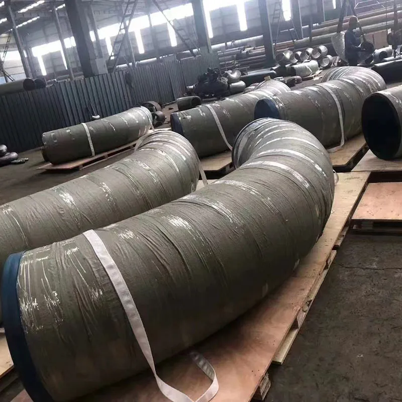
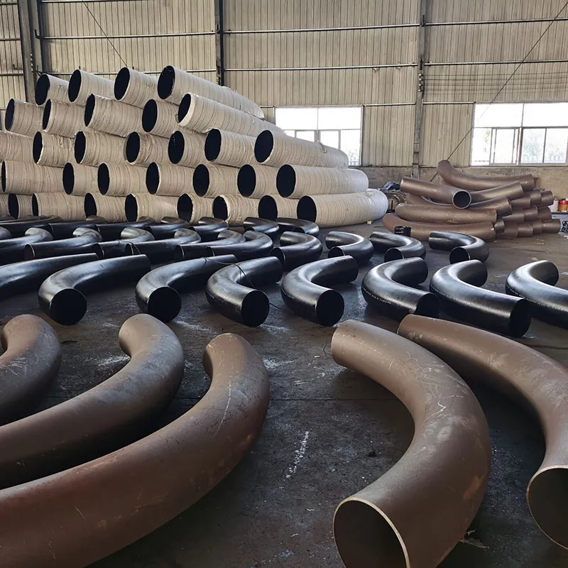
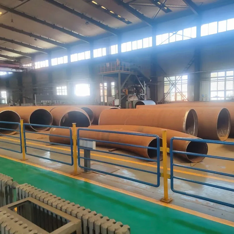
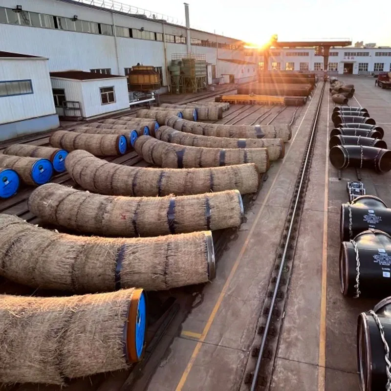
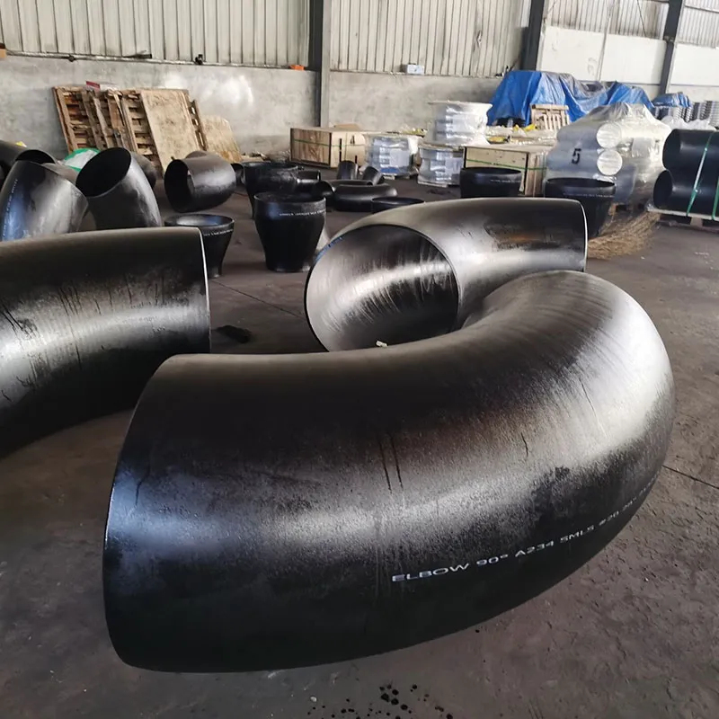
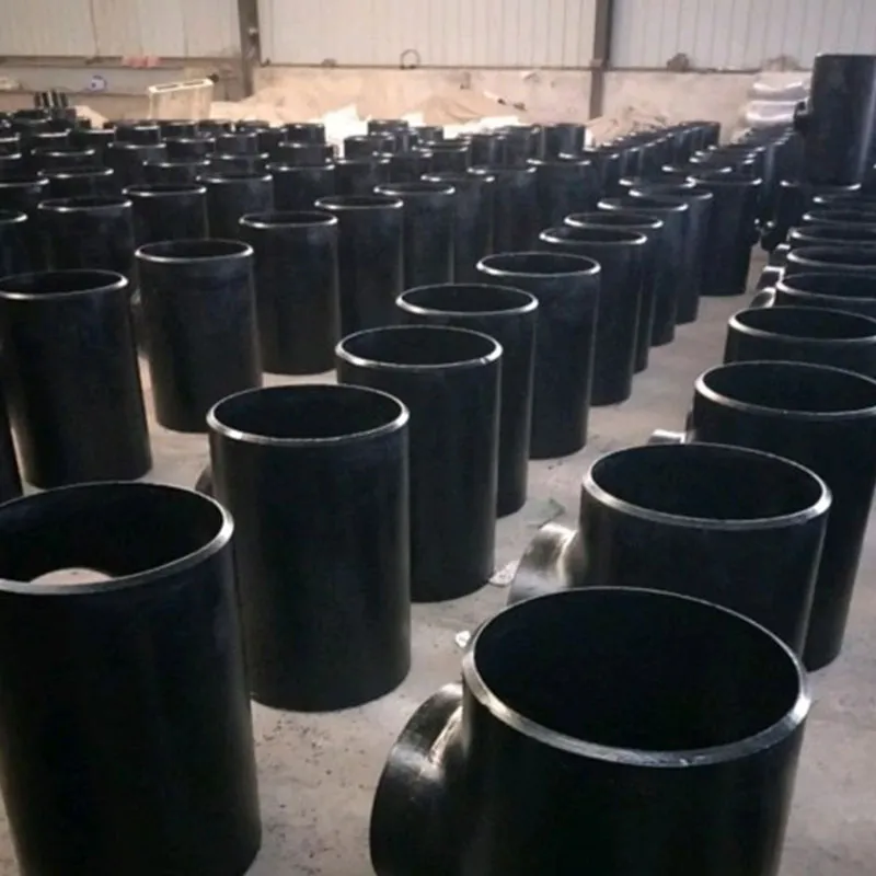
Our high-performance steel pipe bends are engineered for piping systems that require a change in direction with a smoother flow and lower pressure drop than standard elbows. Utilizing advanced cold-bending or induction-heating (Hot Bend) processes, we provide precision-curved solutions for oil and gas transmission, structural engineering, and heavy industrial applications.
Bend Angles:15°, 30°, 45°, 60°, 90°, 135°, 180°, orCustom Degrees.
Bending Radius (R):3D, 4D, 5D, 6D, 8D, 10D, up to 20D (where D is the nominal pipe diameter).
Size Range:1/2" to 72" (DN15 – DN1800).
Wall Thickness:SCH 5S to SCH XXS / STD / XS.
We offer a full range of materials to ensure mechanical integrity and corrosion resistance:
Carbon Steel:ASTM A234 WPB, WPC; ST37.2, A105.
Stainless Steel:ASTM A403 WP304/304L, WP316/316L, 321, 310S.
Alloy Steel:ASTM A234 WP1, WP5, WP9, WP11, WP22, WP91.
Line Pipe Steel:ASTM A860 WPHY 42, 52, 60, 65, 70 (High Yield for Pipelines).
Low Temperature:ASTM A420 WPL6.
All bends are produced and strictly tested in accordance with global industry requirements:
ASME B16.49(Factory-Made Wrought Steel Buttwelding Induction Bends)
ISO 15590-1(Petroleum and Natural Gas Industries — Induction Bends)
ASME/ANSI B16.9(Factory-Made Wrought Buttwelding Fittings)
DIN 2605 / EN 10253
Optimized Flow Dynamics:The large radius reduces friction, turbulence, and internal erosion, extending the life of the piping system.
Structural Integrity:Ideal for "Pigging" in oil and gas pipelines, allowing cleaning tools to pass through easily.
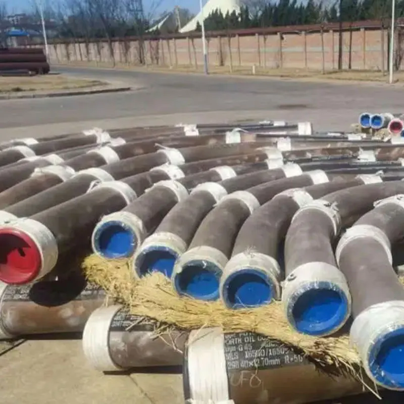
Surface Treatment:Available with Black Vanish, Anti-rust Oil, Hot-dip Galvanized, 3PE Coating, or FBE Coating.
Broad Application:Used in Long-distance Pipelines, Power Plant Construction, Offshore Platforms, and Heavy Structural Frameworks.
Advanced Inspection:100% Dimensional Check, Wall Thinning Analysis, Ovality Testing, and Ultrasonic Testing (UT).
Heat Treatment:Normalizing, Stress Relieving, or Quenching & Tempering (Q+T) to restore material properties after bending.
Certification:Fully compliant withMTC (EN 10204 3.1/3.2); third-party inspection (SGS, TUV, BV) is standard for our export orders.
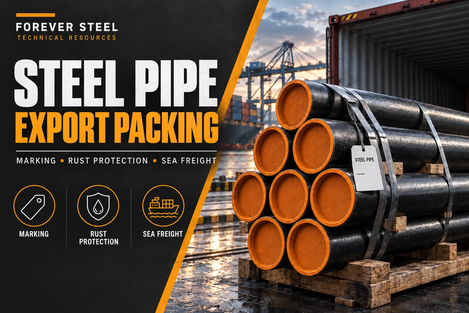
Packaging:Securely packed in seaworthy wooden cases or steel frames with end protection to ensure zero-damage delivery.
For butt-weld fittings, confirm the mating pipe dimensions, end preparation and material traceability before release.
|
Bitmap Nominal Pipe Size(NPS) |
Outside Diameter at Bevel | Center to End | Center to Center | Back to Faces | |||||
| (DN) | |||||||||
| Series A | Series B | 90° Elbows | 45° Elbows | 90° Elbows | 180° Return | 180° Return | |||
| Long Radius (F) | Long Radius (H) | Short Radius (F) | Long Radius (P) | Short Radius (P) | Long Radius (K) | Short Radius (K) | |||
| 15 | 21.3 | 18 | 38 | 16 | - | 76 | - | 48 | - |
| 20 | 26.9 | 25 | 38 | 16 | - | 76 | - | 51 | - |
| 25 | 33.7 | 32 | 38 | 22 | 25 | 76 | 51 | 56 | 41 |
| 32 | 42.4 | 38 | 48 | 25 | 32 | 95 | 64 | 70 | 52 |
| 40 | 48.3 | 45 | 57 | 29 | 38 | 114 | 76 | 83 | 62 |
| 50 | 60.3 | 57 | 76 | 35 | 51 | 152 | 102 | 106 | 81 |
| 65 | 73 | 76 | 95 | 44 | 64 | 191 | 127 | 132 | 100 |
| 80 | 88.9 | 89 | 114 | 51 | 76 | 229 | 152 | 159 | 121 |
| 90 | 101.6 | 108 | 133 | 57 | 89 | 267 | 178 | 184 | 140 |
| 100 | 114.3 | 108 | 152 | 64 | 102 | 305 | 203 | 210 | 159 |
| 125 | 139.7 | 133 | 190 | 79 | 127 | 381 | 254 | 262 | 197 |
| 150 | 168.3 | 159 | 229 | 95 | 152 | 457 | 305 | 313 | 237 |
| 200 | 219.1 | 219 | 305 | 127 | 203 | 610 | 406 | 414 | 313 |
| 250 | 273 | 273 | 381 | 159 | 254 | 762 | 508 | 518 | 391 |
| 300 | 323.8 | 325 | 457 | 190 | 305 | 914 | 610 | 619 | 467 |
| 350 | 355.6 | 377 | 533 | 222 | 356 | 1067 | 711 | 711 | 533 |
| 400 | 406.4 | 426 | 610 | 254 | 406 | 1219 | 813 | 813 | 610 |
| 450 | 457 | 480 | 686 | 286 | 457 | 1372 | 914 | 914 | 686 |
| 500 | 508 | 530 | 762 | 318 | 508 | 1524 | 1016 | 1016 | 762 |
| 550 | 559 | 580 | 838 | 349 | 559 | 1676 | 1118 | 1118 | 838 |
| 600 | 610 | 630 | 914 | 381 | 610 | 1829 | 1219 | 1219 | 914 |
| 650 | 660 | - | 991 | 413 | 660 | 1981 | 1321 | 1321 | 991 |
| 700 | 711 | - | 1067 | 444 | 711 | 2134 | 1422 | 1422 | 1067 |
| 750 | 762 | - | 1143 | 467 | 762 | 2286 | 1524 | 1524 | 1143 |
| 800 | 813 | - | 1219 | 505 | 813 | 2438 | 1626 | 1626 | 1219 |
| Material | Grades |
| Nickel Alloy | ASTM / ASME SB 336 UNS 2200 (NICKEL 200), UNS 2201 (NICKEL 201), UNS 4400 (MONEL 400), UNS 8020 (ALLOY 20 / 20 CB 3), UNS 8825 INCONEL (825), UNS 6600 (INCONEL 600), UNS 6601 (INCONEL 601), UNS 6625 (INCONEL 625), UNS 10276 (HASTELLOY C 276) |
| Carbon Steel | ASTM / ASME A/SA 234 GR. WPB, WPC, WPBW, WPHY 42, WPHY 46, WPHY 52, WPH 60, WPHY 65 & WPHY 70 |
| Low Alloy Steel | ASTM / ASME A/SA 234 GR. WP 1, WP 5, WP 9, WP 11, WP 12, WP 22, WP 23, WP 91 |
| Low Temp Carbon steel | ASTM A420 WPL3, A420 WPL6 |
| Duplex and Super Duplex Steel | ASTM A 815, ASME SA 815 UNS NO S31803, S32205. UNS S32750, S32950. Werkstoff No. 1.4462 |
| Stainless Steel | ASTM A403 WP316/316L, ASTM A403 SA / A 774 WP-S, WP-W, WP-WX 304/304L, ASTM A182 F316L, 304L, DIN 1.4301, DIN1.4306, DIN 1.4401, DIN 1.4404 |
| High Strength Ferritic Steel | ASTM A860 WPHY42, WPHY52, WPHY60, WPHY65, WPHY70 |
| Titanium | ASTM / ASME SB 363 GR. 1, GR. 2, GR. 3, GR. 4, GR. 5, GR. 7, GR. 9, GR. 12, GR. 23 |
| Cu Ni Alloy | C70600 (90:10), C71500 (70:30), C71640 |
| Standard | Type |
| ASME B16.9 | Factory-Made Wrought Buttwelding Fittings |
| ASME B16.28 | Wrought Steel Short Radius Elbows and Buttwelding Returns |
| ASME B16.49 | Factory-Made, Wrought Steel, Buttwelding Induction Bends for Transportation and Distribution Systems |
| MSS SP43 | Wrought and Fabricated Butt-Welding Fittings for Low Pressure, Corrosion Resistant Applications |
| MSS SP75 | Specification for High-Test, Wrought, Butt-Welding Fittings |
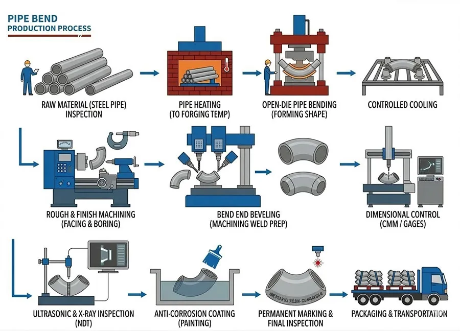
They usually prefer bends when smoother flow transition or larger-radius routing matters to the project. The choice is often linked to pipeline behavior and installation philosophy rather than to simple fitting availability. Typical applications include induction bends for pipeline construction, large radius pipe bends for oil and gas, and custom steel pipe bends for water lines.
They often carry a larger fabrication burden, project-specific geometry, and more careful handling than standard elbows. Buyers are usually paying for a more tailored shape, not just for more steel. This becomes obvious in long-radius pipe bend supply for transmission pipeline and water main installation where geometry affects both cost and freight.
A practical starting question is whether the bend radius is fixed by the project or still flexible. That single answer often changes the whole supply route. That question is useful in cross-country pipeline work, plant piping with smoother flow needs, and large-diameter route changes.
They often overlook transport and packaging implications for larger-radius items. A bend can be easy to specify on paper but awkward to move if that is not considered early. Freight and handling often become major issues in custom pipe bend supply for large-radius pipeline projects.