+8615674993216
 sales@forever-steels.com

 English
 العربية


What to define before you order: radius reference, straight tangents, minimum wall, tolerances and inspection records, plus a copy-ready RFQ checklist.
Order the complete curved member, including its straight tangents and connection geometry.
A structural bend quotation needs more than OD, wall and radius. The order must also define the bend angle, retained straight ends, end orientation, tolerances and remaining wall after forming. Missing any of these can leave a member that cannot fit the assembly or meet its design thickness.
Structural pipe bending produces curved steel pipe or hollow-section members for bridges, trusses, roof arches and steel frames.The delivered member can include a curved middle, permanent straight tangents and prepared connections. This guide covers circular hollow sections (CHS), also described as round hollow structural sections (HSS), with straight ends. A standard elbow fitting is a different scope of supply.
For a steel pipe bending enquiry, attach the structural member drawing and request written confirmation of material, forming route, dimensions and inspection scope.
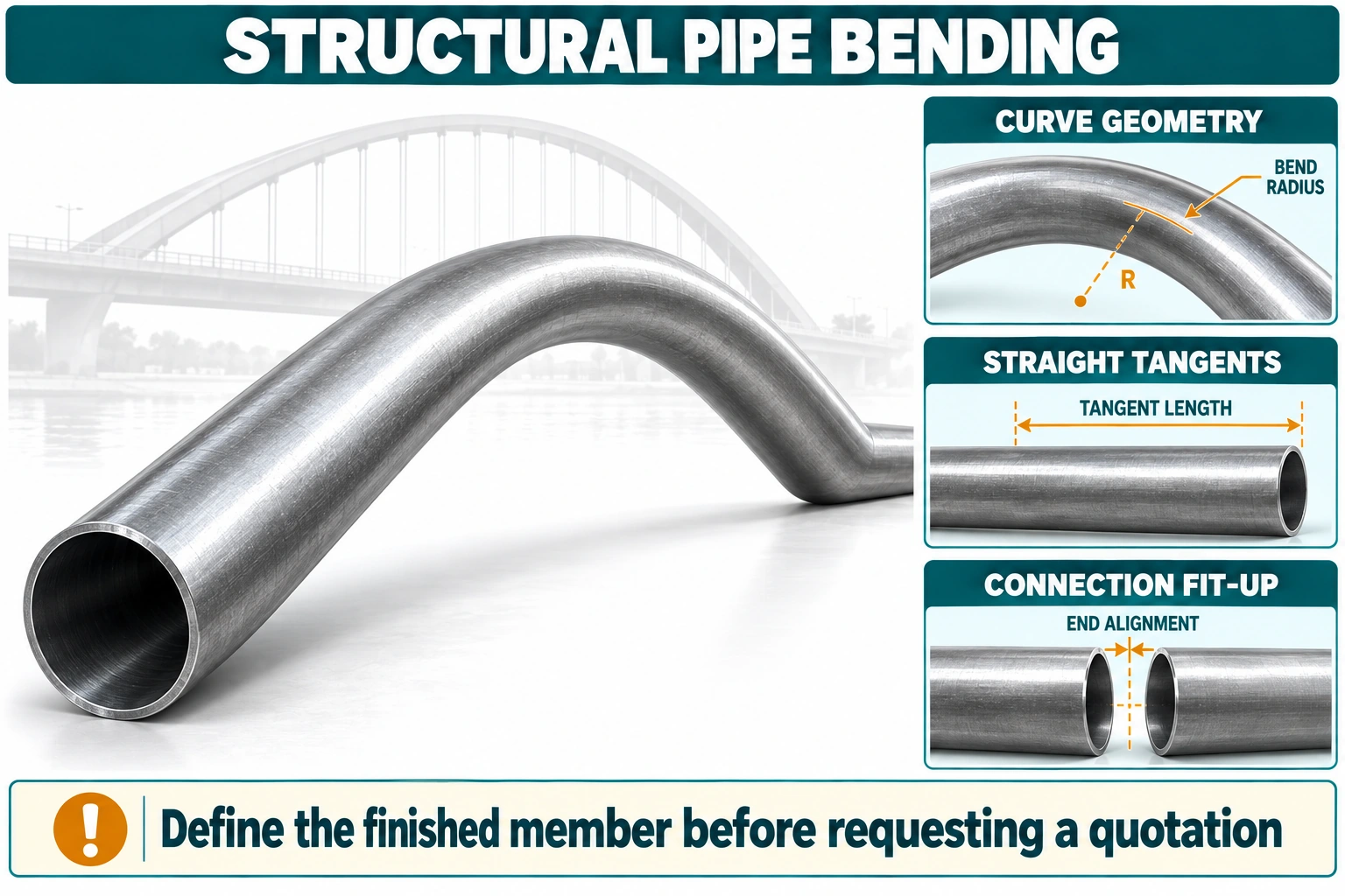
Illustration. A structural curved member with retained straight ends. Concept rendering for procurement explanation; not a project photograph, design drawing or fabrication-capability claim.
Use this list to prepare a quotation request. Each item is covered in detail in the sections below.
|
·Scope of supply:bending only, finished member, fabricated assembly or protected delivery. ·Section and material:OD, wall, grade, specification and supply condition. ·Curve geometry:radius reference, bend angle, units and drawing revision. ·Straight tangents:permanent L1 and L2, kept separate from gripping allowances. ·Forming route:cold or hot method, starting blank and process allowances. ·Acceptance criteria:tolerances, section distortion, wall thinning and minimum remaining wall. ·Connections and records:end preparation, inspection reports, finish, packing and traceability. |
Buy a drawing-defined structural member rather than relying on the terms pipe bend or bent pipe alone.Structural pipe bending or HSS bending describes the process; bent steel pipe members and curved CHS members describe the resulting components. Pipe bends is a broader commercial term that can also describe pressure-piping components.
The first distinction is what the supplier must deliver. A bending-only subcontract can return an overlength member for the fabricator to trim. Another order can require a finished member with retained tangents, bevels, saddle cuts, holes, end plates or coating. Those are different scopes, even when the initial pipe section and radius match.
|
Scope offered |
Expected deliverable |
Clarification before order |
|
Bending only |
Curved section, potentially with excess material |
Who supplies pipe, trims ends and performs final dimensional acceptance? |
|
Finished bent member |
Approved curve plus retained straight ends |
Are L1, L2, end cuts and drawing datums included? |
|
Fabricated assembly |
Bent members with specified connections or welded attachments |
Who controls welding, assembly geometry and inspection? |
|
Protected delivery |
Agreed fabricated shape with specified preservation or coating |
Which surfaces, packing supports and touch-up records are included? |
Identify the member mark and its position in the assembly. A bridge arch segment, brace and roof chord can have different connection and fatigue requirements; carry the designer's requirements into the order.
Use the approved structural design and fabrication documents as the order basis. AISC's curved-steel resources address the coordination of design, detailing and fabrication. [1]
The material specification for the starting section and the acceptance requirements for the bent member need to be stated separately.Identify the exact grade, section standard, supply condition and documentation required by the structural design.
When selecting structural hollow sections, confirm the outside dimensions and nominal wall before discussing forming. ASTM A500 and EN 10210 or EN 10219 are examples of specification families encountered in structural hollow-section procurement; they should not be treated as interchangeable grades or forming approvals. The project decides which material and edition are acceptable.
For bridge work, include the bridge owner's fabrication, welding, toughness and fatigue requirements where applicable. Building-HSS guidance alone does not establish bridge acceptance.
Request traceability from the original material record to each member mark after cutting and forming. If the bending route involves heat, agree which records demonstrate the required final condition. If additional tests are required, state their method, location, frequency and acceptance basis. Do not imply that a parent-material certificate alone certifies the final structural performance.
For a member with a circular centreline arc, define the radius reference and enough independent dimensions to reconstruct the curve.State whether the radius follows the member centreline, inside face or outside face. Use explicit units and the approved drawing revision.
For an undeformed round section of outside diameter D, the centreline bend radius is R. The radius to the outer pipe surface on the concave side (intrados) is R − D/2; on the convex side (extrados), it is R + D/2. These are radii of the member outline in the bending plane, not pipe-bore radii. Actual section distortion must be checked separately. [2][3]
AISC's geometry guidance identifies useful combinations including radius with angle, radius with arc length and chord with rise. It also states that tangent lengths need separate dimensions. The buyer should choose one controlling combination and use other dimensions as checks; inconsistent rounded values should not all be treated as independent mandatory dimensions. [2]
|
Dimension |
Definition to state on the drawing |
Procurement consequence |
|
Centreline radius R |
Radius to the section centreline |
Establishes the curve without an inside/outside-reference ambiguity |
|
Bend angle θ |
Change of centreline direction through the bend; equal to the central angle for this circular arc |
Establishes arc extent; not the supplementary angle between the two arms |
|
Chord c |
Straight distance between defined arc-end work points |
Useful for checking the curved portion |
|
Rise or mid-ordinate h |
Perpendicular centreline distance from the chord to the arc midpoint |
Useful for checking the shape on a defined plane |
|
Arc length s |
Centreline distance along the circular segment |
Supports developed-length planning |
|
Straight tangent lengths L1 and L2 |
Permanent straight lengths from tangent points to finished end faces |
Establishes end location and connection space |
Here, a 60° bend means a 60° change of direction and a 60° central arc angle. The angle between the two outward-pointing straight arms is 120°; do not substitute that supplementary angle into the arc-length calculation. AISC uses degree of bend, while ISO defines bend angle by directional change. [2][3]
For a three-dimensional or variable-radius member, one radius and a sketch are insufficient. Provide a controlled model or coordinate schedule, the unit system, origin, axis directions and end-frame orientation. State which file controls if the model and drawing differ. Identify each curved segment, intermediate straight and transition rather than forcing a freeform shape into a single-radius description.
Structural curves can be much gentler than a familiar 3D or 5D pipeline bend. Do not make those commercial labels the organizing principle of a bridge-member RFQ. If a D multiple is used, define D as the actual outside diameter or another explicitly adopted convention and also give R in millimetres.
For example, a 406.4 mm OD member with R = 6,000 mm has R/D approximately 14.76. That ratio is descriptive. It does not prove formability, structural adequacy or a supplier's minimum-radius capability. The section wall, grade, process and acceptable deformation must be reviewed together.
A permanent straight tangent is part of the delivered member; a gripping or run-out allowance is additional material required by the forming process.An order that mixes these two lengths can produce a short component or unnecessary material cost.
Show each tangent point and dimension L1 and L2 along the member centreline to the final end faces. State whether those faces are square, bevelled or cut to a connection profile. If the drawing includes an allowance for later trimming, label it separately from the final installed length.
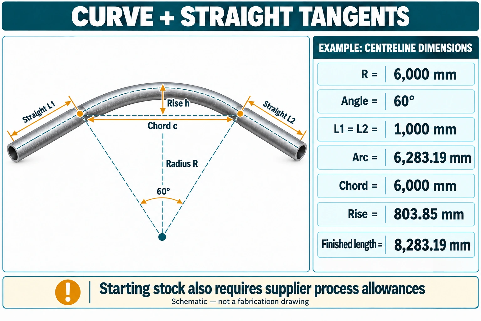
Figure 1. The circular arc and both permanent tangents are separate parts of the finished member. The example uses centreline geometry; starting blank length additionally depends on the supplier's process. Diagram is schematic.
Steel Tube Institute's discussion of HSS bending notes the need for overlength material because the entire starting member cannot necessarily be curved. The amount is process- and member-dependent. Ask the bender for the required starting blank and discard allowance rather than copying a generic allowance from another job. [4]
Assume an illustrative circular CHS member withR = 6,000 mm,θ = 60°, andL1 = L2 = 1,000 mm. These are example drawing inputs, not recommended bridge dimensions. The equations for the circular segment are:
· Arc length: s = R × θ × π/180.
· Chord: c = 2R × sin(θ/2).
· Rise: h = R × [1 − cos(θ/2)].
· Finished developed centreline length: L = L1 + s + L2.
|
Check |
Calculated result |
Boundary of the calculation |
|
Curved centreline arc |
6,283.19 mm |
Includes the circular part only |
|
Chord between tangent points |
6,000.00 mm |
Excludes permanent straight tangents |
|
Rise above that chord |
803.85 mm |
Measured to the arc centreline |
|
Finished developed centreline length |
8,283.19 mm |
Arc plus two 1,000 mm tangents |
|
Starting stock length |
Supplier to propose |
Includes process allowances and any trimming plan |
The developed centreline length is neither the shipping envelope nor a guaranteed stock-cutting instruction. It also does not describe the chord between the finished ends. End-face positions depend on tangent directions, while the transport envelope additionally includes section diameter, supports and protection. Request those dimensions separately.
Cold bending forms the member mechanically without deliberate heating; hot bending uses heating to assist forming.Roll bending and selected press or incremental methods can be cold routes. Induction bending is a heated route that concentrates heat in a short band. AISC lists conventional hot bending and induction bending separately; name the specific process in the RFQ. [5] Steel Tube Institute describes these distinctions and the dependence of achievable curvature on method, section and tooling. [4]
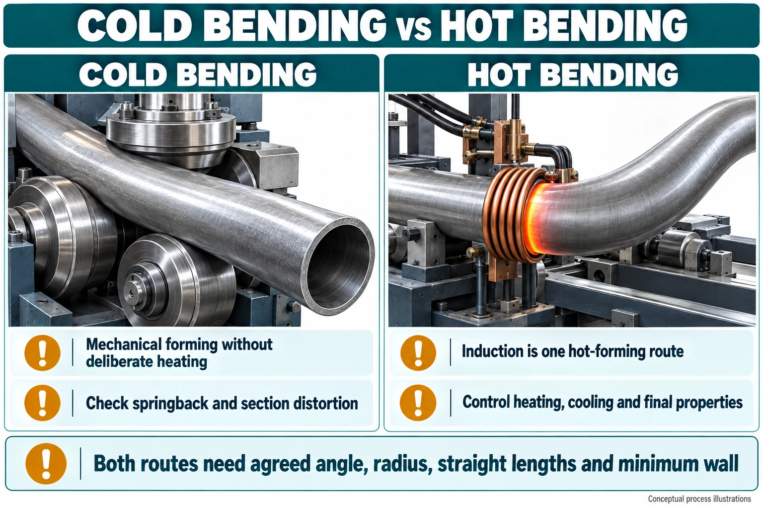
Conceptual process illustrations. The equipment shown explains the process families and does not represent Forever Steel equipment or a qualified project procedure.
|
Buyer question |
Cold bending |
Hot bending including induction |
|
How is the curve formed |
Mechanical force without a deliberate heating cycle |
Mechanical forming with an approved heating cycle |
|
Main process controls |
Tool support, passes, springback compensation and section distortion |
Heating method, temperature control, travel rate and cooling procedure as applicable |
|
Wall and surface checks |
Verify remaining wall, ovality, local flattening and intrados wrinkles |
Verify remaining wall, ovality and local condition, including heated and transition zones |
|
Material evidence |
Confirm suitability for forming strain and any project-required final tests |
Confirm final properties and any required heat treatment or tests against the approved procedure |
|
Basis for selection |
Actual OD, wall, grade, radius, tangents and acceptance requirements |
The same member requirements plus the agreed thermal and property controls |
Request evidence for the supplier's proposed method on the actual OD, wall, grade and radius. For a heated route, agree temperature and cooling records, final property tests and any heat treatment required by the approved procedure. Barnshaws describes local heating in its induction process. [6]
No bending method is automatically best for every structural pipe.Give the supplier the section, wall, grade, radius, tangent arrangement and allowed deformation, then request a proposed process with relevant evidence.
Use the process names below in the enquiry. AISC and Steel Tube Institute distinguish roll bending, point bending, synchronized incremental cold bending, rotary-draw bending and induction bending. A mandrel provides internal support; it is not a separate thermal process family. [4][5]
|
Forming route |
Procurement use to discuss |
Evidence or constraint to clarify |
|
Three-roll bending or pyramid rolling |
Smooth large-radius structural curves |
Tooling, end run-out, repeatability and achievable cross-section |
|
Point bending or gag pressing |
Large-radius curves formed by discrete press loads |
Local changes in curvature, support arrangement and survey method |
|
Synchronized incremental cold bending |
Curves formed by coordinated repeated loading |
Process-specific evidence of profile and cross-section control |
|
Rotary-draw bending with mandrel support where required |
Tubes formed around a die, with internal support where needed |
Die radius, mandrel access, tooling and retained straight lengths |
|
Induction bending |
Locally heated forming where approved for the member |
Temperature control, cooling route and post-forming property verification |
Cold forming can introduce strain, residual stresses and section distortion. Heated forming also needs thermal and final-property controls. Agree the required tests or treatment for the selected material and procedure.
Ask whether the process will form the complete member in one piece. A proposed welded splice, change of radius or segmented substitute needs drawing and engineering approval. A similar silhouette is not sufficient evidence that the substitute carries loads or connects in the same way.
Curve accuracy and cross-section accuracy are separate acceptance questions.A member can follow the intended radius while its section has flattened, or have an acceptable section while the ends miss their connection work points.
Steel Tube Institute's distortion guidance explains that straight-member dimensional limits do not automatically describe the tolerances achievable after curving. It highlights the importance of connections when agreeing allowable cross-sectional change. Use that distinction to establish project-specific post-bend limits before manufacture. [7]
|
Acceptance category |
What to define |
Why it matters |
|
Global curve |
Reference plane, centreline check points and permitted profile deviation |
Assembly alignment and architectural shape |
|
End geometry |
End coordinates, orientation and retained tangent length |
Joint position and fit-up |
|
Section shape |
Measurement locations, ovality or section-dimension limits |
Local behaviour and mating-component compatibility |
|
Local condition |
Wrinkles, dents, gouges, cracking and surface marking criteria |
Structural evaluation and appearance |
|
Finished connections |
End cuts, holes, plates, weld preparations and datums |
Fit-up with the rest of the steelwork |
For round members, inspect ovalization (the deformation), ovality or out-of-roundness (the measured result), local flattening, wall changes and surface imperfections at the locations required by the agreed inspection plan. Specify the definition and reference diameter if ovality is reported as a percentage. For the example below, ovality = 100 × (Dmax − Dmin)/Dref. State Dref and the measurement plane in the order: formulas using nominal, original or mean diameter are not interchangeable.
As an arithmetic example, Dmax = 410 mm and Dmin = 403 mm give approximately1.72%when Dref = 406.4 mm. That number is not a permissible structural ovality. Acceptance depends on the approved design, location, connection and manufacturing agreement.
The purchase order must state the bend angle, centreline radius, allowed angle deviation, permanent straight lengths, thinning requirements, intrados wrinkle criteria and minimum remaining wall.A drawing with only a nominal radius and pipe size leaves important acceptance decisions unresolved.
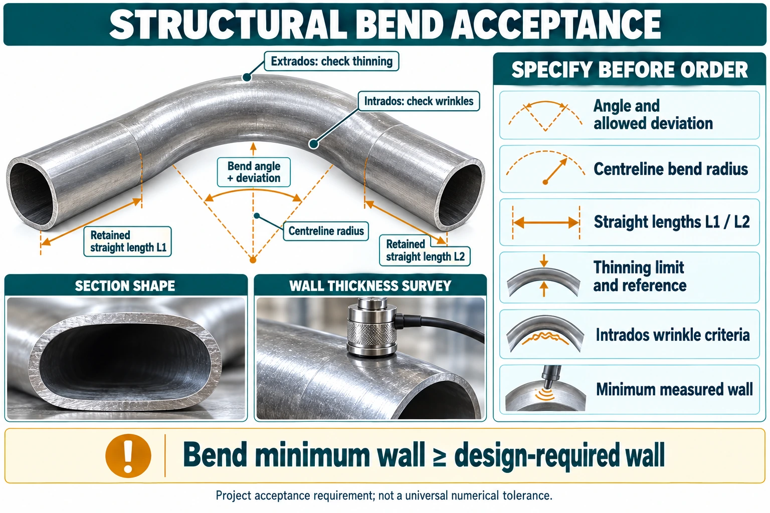
Figure 2. Specify geometry, wall thinning, intrados condition and minimum remaining wall separately. Section distortion is exaggerated for explanation. The wall statement is the project procurement requirement described below; no universal numerical tolerance is implied.
|
Critical indicator |
Requirement to agree before manufacture |
Release evidence |
|
Bend angle |
Nominal change-of-direction angle and its measurement convention |
Actual finished angle after unloading |
|
Bend radius |
Centreline, inside or outside reference and permitted deviation |
Survey of agreed work points or approved template check |
|
Bend angle tolerance |
Permitted positive and negative deviation from the nominal bend angle, in degrees |
Recorded actual deviation and end orientation |
|
Retained straight lengths |
Finished L1 and L2 from tangent points to final end faces |
Actual lengths excluding removable gripping allowances |
|
Wall thinning percentage |
Whether a maximum percentage reduction is guaranteed, its actual starting-wall reference, locations and acceptance limit |
Traceable before-and-after measurements or an explicitly approved reference method |
|
Intrados wrinkling |
Whether wrinkles are prohibited; otherwise the designer-approved size, location and assessment criteria |
Visual examination and measured profile where required |
|
Minimum remaining wall |
At every inspected location, bent-member wall must meet the project design-required minimum |
Calibrated thickness survey with the lowest measured value and location identified |
Require t_min,bend ≥ t_min,required: the minimum measured wall after bending must meet the project-specified minimum finished wall thickness.For the requirement adopted in this guide, that acceptance value must be no less than the thickness required by the approved design for the straight member. Where the bend or connection needs more wall, use the greater value. State the numerical acceptance value in millimetres on the drawing and order.
Keep three values separate: nominal wall thickness ordered from the mill, design wall thickness used for structural calculations, and the project-specified minimum measured wall after bending. In HSS design, design wall thickness can be a prescribed calculation value related to the product specification; it is not automatically a measured acceptance limit. The designer must state the finished-wall limit explicitly. Starting tolerances and anticipated thinning must leave enough actual wall to meet that limit. [8]
Passing the wall thinning percentage limit does not replace the minimum-wall check.If the agreed reference is the measured original wall at corresponding locations, wall thinning percentage = 100 × (t_before − t_after) / t_before. If a different reference is adopted, name it explicitly; percentages calculated from nominal and measured starting wall are not directly interchangeable.
For example, reducing an actual 12.0 mm wall to 10.8 mm gives 10% thinning. If the approved design requires 11.0 mm, that bend fails the minimum-wall condition even if a separately agreed thinning limit allows 10%. These values are arithmetic examples, not recommended manufacturing tolerances.
Agree thickness-survey locations around and along the bend, including extrados, intrados, sidewalls and transitions. Record the lowest measured value and its location, rather than an average or one convenient reading. Check intrados wrinkles separately from extrados thinning; state the measurement method and treatment of measurement uncertainty in the inspection plan.
Agree where end cuts, saddle profiles, bolt holes and plates will be produced relative to the bending operation. Work done on a straight blank can move or distort during forming. Work done afterwards needs datums that reconcile with the curved member's final geometry.
For welded pipe, state any required longitudinal seam orientation relative to the curve and connection. A round section has no preferred geometric bending axis, but seams, attachments and end preparations can still create a required rotational orientation. Do not rotate a member to improve fit-up without checking those features.
Where tolerances are tight, consider a first article, connection gauge or trial assembly with the relevant mating parts. Record the agreed method and acceptance conditions. Forcing a delivered member into place with unapproved heating, jacking or trimming can introduce new structural or dimensional problems rather than close the original nonconformity.
The dimensional report must identify the drawing revision, support arrangement, datum, measurement method and actual results.Compare measured curve and end coordinates with the approved nominal values.
A template can be suitable for a simple planar curve. A survey or three-dimensional measurement method may be appropriate for large, multi-axis or freeform members. Select the method according to the geometry and required accuracy. The report should state the datum, support condition, measurement equipment and actual results at agreed points.
Long curved members can deflect under their own weight. Specify the support arrangement for inspection so the buyer and supplier do not compare a supported shop measurement with an unsupported site measurement as if they were identical. If temperature corrections or a reference temperature matter for the required accuracy, agree how they will be handled.
|
Release evidence |
Minimum procurement question |
|
Material identity |
Does the certificate cross-reference the delivered member mark? |
|
Approved process |
Was the agreed bending route used, with any required qualification? |
|
Dimensional report |
Are actual curve and end coordinates compared with the correct revision? |
|
Section and local-condition report |
Were specified locations and distortion criteria checked? |
|
Connection and weld records |
Do included fabrication and examinations match the ordered scope? |
|
Surface-treatment records |
Is the specified finish complete, including permitted repairs? |
|
Packing and identification list |
Can the receiving team identify and handle every member correctly? |
Use an inspection and test plan, or ITP, to identify hold and witness points. A first-article approval is most useful before the rest of a repeat batch is completed. State who approves deviations and when the supplier may proceed. A late drawing revision should trigger a documented review of affected material, tooling and completed work.
Packing is part of protecting the member's shape and connection surfaces.Request the actual three-dimensional shipping envelope, gross weight, centre of gravity information where needed, and the proposed support and restraint arrangement.
Long retained tangents can affect trailer length, stacking and lifting. Nested curved members can require separators to protect coated surfaces and prevent local contact damage. Agree lifting points and support locations with the responsible fabricator or engineer; do not assume that a convenient straight end is an approved lifting point.
For architecturally exposed structural steel, state the required appearance and review method. Tool marks, weld dressing and surface transitions can have commercial consequences even when the geometry passes. Agree a sample or mock-up if the appearance requirement cannot be expressed adequately through a simple coating description.
If hot-dip galvanizing is specified, coordinate venting, drainage, bath access and any dimensional recheck with the fabricator and galvanizer. For painted members, define preparation, coating system, connection masking and repair requirements. The coating decision should fit the structural detail and environment rather than copy a buried-pipeline specification.
Link the packing marks to the erection sequence and assembly drawings. Mirror-image or similar-radius pieces need distinct identification. A complete packing list that does not tell the receiving team which piece is left-handed or right-handed can still delay assembly.
Compare the price of the same finished member and delivery scope.Separate starting material, forming, trimming, connections, inspection, finish and transport in the comparison.
|
Comparison item |
Require in every offer |
Potential hidden difference |
|
Section and material |
OD, wall, grade and adopted specification |
Different starting section or substitute material |
|
Geometry |
Drawing revision, radius reference, angles and L1/L2 |
Arc-only price compared with a finished member |
|
Process allowances |
Starting blank, run-out, trimming and scrap responsibility |
Extra length supplied or charged later |
|
Acceptance |
Profile, section, connection limits and inspection method |
Tighter criteria excluded from the original quote |
|
Fabrication |
Included end cuts, plates, holes, splices and welding |
Bending-only service compared with complete fabrication |
|
Delivery |
Surface protection, packing, envelope and delivery term |
Shop completion compared with approved, deliverable supply |
Ask for a sample inspection report for a comparable member. Confirm who performs bending and who performs fabrication. A maximum machine diameter alone does not demonstrate capability for your combination of OD, wall, grade, radius and straight lengths.
Request dates for drawing approval, material, first article, production, inspection and shipment. Compare quotations against the same drawing revision and acceptance schedule.
|
RFQ field |
Information to provide |
|
Project and item |
Application, member mark, quantity and revision |
|
Section |
Round CHS/HSS outside diameter and wall, or full hollow-section dimensions |
|
Material |
Grade, specification, supply condition and document requirements |
|
Circular geometry |
Radius reference, nominal angle, permitted angle/radius deviations, chord/rise checks and units |
|
Permanent straights |
L1 and L2, tangent points, final end faces and trimming allowances |
|
Complex geometry |
Controlled model, coordinates, origin, axes and end orientation |
|
Connections |
End cuts, bevels, plates, holes, seam orientation and fabrication responsibility |
|
Acceptance |
Profile and end tolerances, wall thinning percentage limit and reference, intrados wrinkle criteria, minimum wall meeting design-required thickness, section shape and appearance |
|
Process and inspection |
Cold or hot route and specific method, thermal/property controls where applicable, thickness survey, first article and ITP |
|
Delivery |
Finish, packing, transport envelope, destination and erection identification |
“Please quote eight curved CHS members for a bridge steelwork package, drawing SB-101 Rev A. Section OD 406.4 mm × nominal wall 12.5 mm; material grade and supply specification as stated in the attached structural specification. Single-plane circular centreline radius R = 6,000 mm, bend angle 60° (change of direction), retained straight tangents L1 = L2 = 1,000 mm to the finished square end faces. Reference chord and rise apply between the tangent points. Propose a cold or hot forming route, its specific method, starting blank length and process allowances separately. Confirm bend angle tolerance and radius tolerance, retained straight lengths, the wall thinning percentage limit and reference, intrados wrinkle criteria, and thickness-survey coverage against the attached acceptance schedule. The minimum measured wall after bending shall meet the minimum finished-wall value stated in the attached acceptance schedule. That value shall not be less than the approved required thickness for the straight member; any greater local bend or connection requirement also applies. Identify any proposed splice. Confirm the supplied scope for end preparation, post-bend geometry and section inspection, traceability, surface protection and transport supports. Submit technical deviations and exclusions with the quotation.”
No. A structural order defines the complete curved member, its retained straight tangents and connections. An elbow is a fitting.
Provide the section size and grade, controlled curve geometry, tangent lengths, end orientation, connection scope, post-bend acceptance criteria, quantity and delivery requirements. For a multi-axis member, include a controlled model or coordinate schedule.
No. Dimension permanent straight tangents separately and distinguish them from removable gripping or run-out material. Confirm whether the supplier will trim to final length or leave an agreed allowance for the fabricator.
No. Check the end locations, end orientation, section distortion, local condition and included connections as well. A radius measurement alone cannot prove assembly fit-up or structural suitability.
It identifies the starting material when traceability is maintained. Acceptance of the formed component also requires the agreed geometry, processing and inspection evidence. Structural adequacy remains subject to the adopted design and fabrication requirements.
Not automatically. ASME describes B16.49 as a pipeline induction-bend standard. Bridge and building members require their applicable structural design, material, fabrication and inspection basis. Any additional bend standard must be selected deliberately by the responsible project team. [9]
No. Check the minimum measured wall separately against the approved design-required minimum. A bend can satisfy its wall thinning percentage limit and still be too thin for the design. State both conditions and the thinning reference in the order.
Cold bending uses mechanical forming without deliberate heating. Hot bending uses a controlled heating step; induction is one such route. Select the route against the actual material and geometry, and agree final dimensional, wall and property evidence before production. [4][6]
Send Forever Steel the member drawing, material specification, acceptance requirements (bend angle, radius, angle tolerance, retained straight lengths, wall thinning limit, intrados wrinkle criteria and minimum remaining wall), quantity and destination. Request a proposal identifying the forming method, included fabrication, inspection records and deviations.
Submit a structural pipe bending enquiry with the completed RFQ schedule.
· ASTM A500 Structural Tubing Guide
· EN 10219 and EN 10210 Differences for Structural Hollow Sections
· Steel Pipe Export Packing and Marking Guide
1. AISC Curved Steel Resources. Curved-member design and fabrication guidance.
2. AISC Curved Steel Geometry. Geometric dimension combinations and separate tangent dimensions.
3. ISO 15590-4:2019 public terminology. Used only to cross-check bend angle, radius, tangent, intrados, extrados and wall thinning terminology; its pipeline delivery requirements are not adopted as structural acceptance rules.
4. Steel Tube Institute Bending of Hollow Structural Sections. Forming considerations and additional starting length.
5. AISC Curved Steel Technical Information. Named bending methods and their distinctions.
6. Barnshaws Tube and Pipe Bending and Barnshaws Induction Bending. Specialist descriptions of forming routes; supplier-specific capabilities are not transferred to this guide.
7. Steel Tube Institute Minimizing Distortion in Curved HSS Members. Post-bend section variation and connection considerations.
8. Steel Tube Institute HSS Design Wall Thickness Discussion. Distinction between nominal and design wall thickness; not a post-bending inspection specification.
9. ASME B16.49 Official Scope. Pipeline scope boundary.