+8615674993216
 sales@forever-steels.com

 English
 العربية


A flange pressure class does not specify the bore needed at the pipe weld. Check pressure–temperature suitability using the applicable flange standard and material, then coordinate the flange weld-end bore with the pipe dimensions and approved joint detail. An order stating only nominal size and Class or PN leaves an important fit-up question unanswered. [1]
For buyers ordering pipe and steel pipe flanges together, the most useful document is a shared connection schedule: one agreed set of pipe dimensions, flange requirements, end preparation and drawing revisions. This guide explains what to put in that schedule and what to verify before fabrication.
| Check | Information that must be agreed |
|---|---|
| Pipe | Product standard, material, nominal size, OD, wall and applicable tolerances |
| Flange | Standard and edition, type, material, size and Class or PN |
| Weld-end bore | Required bore, tolerance and relationship to the mating pipe |
| End preparation | Approved joint drawing and applicable fabrication requirements |
| Sealing interface | Facing, gasket specification and mating flange compatibility |
| Inspection | Traceability, dimensional records, inspection documents and agreed hold points |
A bore difference can create an internal step at the joint. Its significance depends on the joint design, service, fabrication rules and acceptance criteria. A step can complicate fit-up or produce a less smooth internal flow path; it does not automatically prove that every joint will fail, erode or be rejected by radiography.
Keep three problems separate: different internal diameters, off-centre alignment and uneven local wall thickness. Matching two calculated nominal bores addresses only the first at a nominal level. The actual mating ends still need inspection against the approved joint requirements.
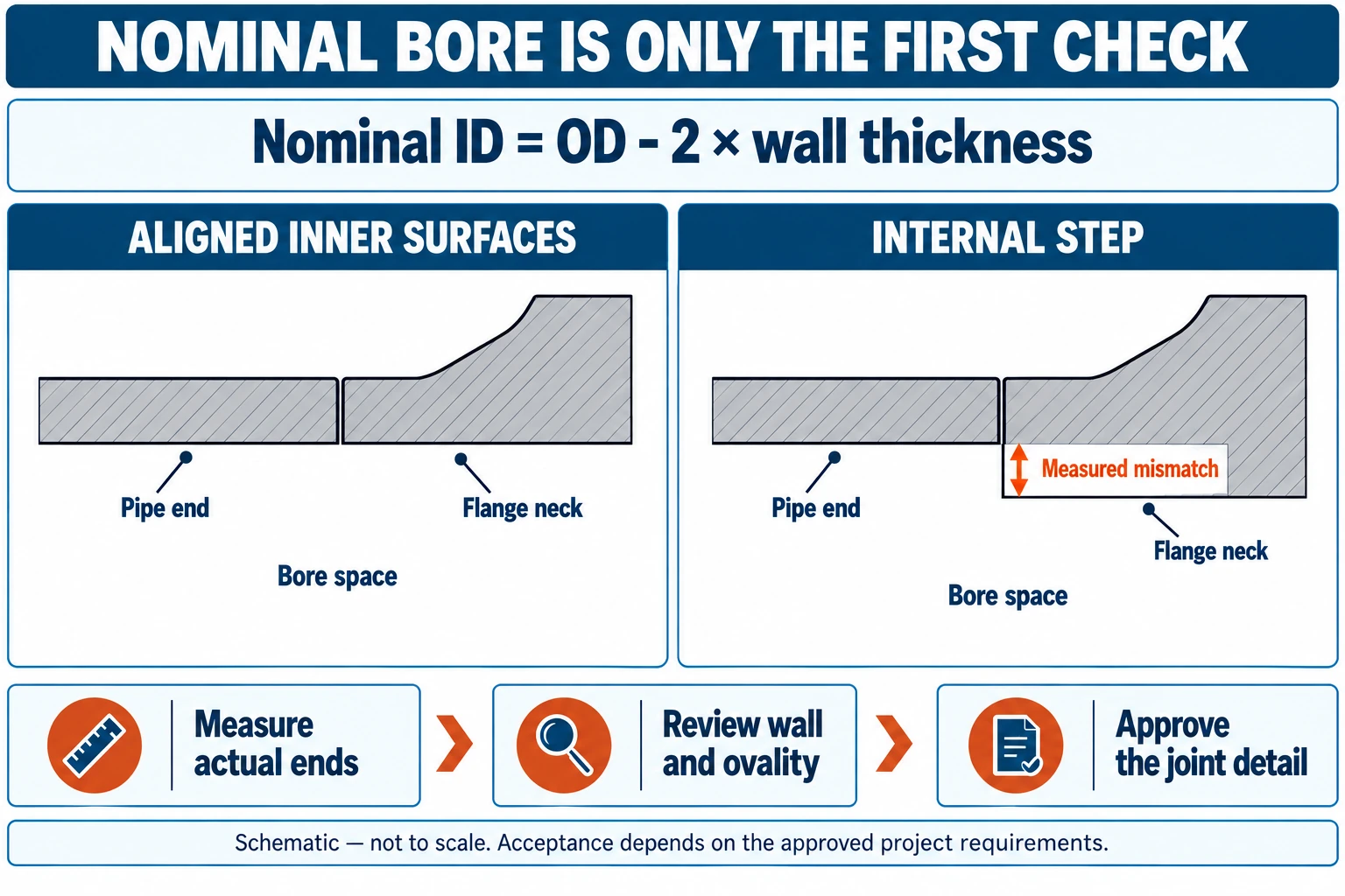
Figure 1. Conceptual internal step at the weld interface. The highlighted step is illustrative, not an allowable mismatch. The drawing is not to scale and does not prescribe bevel geometry.
Pressure rating, pipe wall selection and weld-end fit-up are linked design decisions, but they are not interchangeable labels. ASME B16.5 covers pressure–temperature ratings along with flange materials, dimensions and other requirements. A Class designation should therefore be interpreted with the material and temperature, not as a stand-alone pressure value. [1]
| Decision | What it establishes | What it does not establish by itself |
|---|---|---|
| Flange Class or PN | Rating designation under the applicable flange system | The mating pipe’s exact wall or measured ID |
| Pipe schedule or specified wall | Nominal dimensional selection for the pipe | Acceptable pressure for every material and service |
| Flange weld-end bore | Internal dimension at the mating end | Approval of the complete welded joint |
| Joint acceptance detail | Required alignment, preparation and acceptance basis | Adequacy of an unreviewed material substitution |
Avoid a table suggesting that a particular flange class always uses one schedule. Pipe wall selection belongs to the applicable design calculation and specification; the flange must then be ordered to the required connection details. “Class 150 equals Schedule 40” is not a purchasing rule.
For a circular tube or pipe represented by a uniform wall, the nominal arithmetic is:
Inside diameter = outside diameter − 2 × wall thickness.
This calculation is useful for spotting a drawing inconsistency. It is not a measurement report, and it does not include wall variation, ovality or centreline offset.
The following dimensions are invented for illustration. They are not an ASME nominal pipe size, a schedule table, a recommended wall or an approved design.
| Illustrative component | OD | Wall at the end | Calculated ID |
|---|---|---|---|
| Pipe end A | 100 mm | 6 mm | 100 − 2 × 6 = 88 mm |
| Mating end B | 100 mm | 9 mm | 100 − 2 × 9 = 82 mm |
If these idealized ends are concentric, their bore diameters differ by 6 mm and the radial internal step is (88 − 82) ÷ 2 = 3 mm. This is geometry only. It gives no acceptance limit and no permission to machine either component.
For an actual NPS/schedule order, retrieve OD and nominal wall from the contractually applicable dimensional standard, then apply the product tolerances and approved joint requirements. This article does not reproduce an NPS 4 Schedule 40/80 table because the relevant licensed dimensional table has not been checked. ASME’s public B36.10 preview confirms the dimensional standard’s identity, but a contents page does not verify individual table values. [4]
Under either system, write the connection dimensions clearly enough for the supplier to check the mating ends. An ASME order commonly uses NPS and schedule; an EN order may use DN/PN and specified dimensional details. Neither naming convention removes the need to confirm actual OD, wall and flange weld-end requirements.
| Field | ASME-based inquiry | EN-based inquiry |
|---|---|---|
| Flange specification | Applicable ASME standard, edition, type and Class | EN 1092-1 edition, flange type and PN |
| Pipe designation | NPS plus schedule or specified wall | DN plus actual OD and specified wall |
| Connection detail | Bore and end preparation tied to drawing | Bore and end preparation tied to drawing |
| Facing and gasket | Matching specifications explicitly stated | Matching specifications explicitly stated |
EN 1092-1 concerns PN-designated steel flanges. Type 11 identifies the welding-neck form in manufacturer product documentation. Confirm the required dimensions and facing under the actual standard and drawing instead of treating the type number as a complete specification. [5][7]
Nominal compatibility is the beginning of the review, not the final inspection. Product tolerances, local geometry and procurement changes can all affect the mating ends. The inspection plan should identify the measurements needed for the specific joint rather than rely on a single catalogue value.
| Source of mismatch | Buyer’s preventive action |
|---|---|
| Pipe wall tolerance | Identify the actual product specification and relevant wall requirements; do not assume a universal negative tolerance |
| Ovality or local wall variation | Agree where and how the end geometry will be measured |
| Flange ordered for another wall | Put the pipe wall and flange bore on the same connection schedule |
| Pipe specification revised later | Require a linked review of flange bore and joint detail |
| Separate suppliers using different drawings | Issue one controlled revision and require acknowledgement |
| Unapproved end machining | Require engineering disposition before material is removed |
For example, a wall below nominal can increase the local inside dimension if outside geometry is otherwise unchanged. The amount cannot be predicted from a generic “steel pipe tolerance”: it must be assessed using the applicable product specification and measured end.
Do not correct a mismatch by telling the workshop to “grind until it fits.” Establish the applicable end-preparation standard and piping or fabrication code, then obtain the approved joint detail and acceptance requirements. Removing material can affect the required wall and component integrity.
ASME B16.25 addresses butt-welding end preparation, including preparation for heavy-wall components. Where ASME B31.3 governs the project, its fabrication and examination requirements also form part of the review. Their public scope pages do not establish a universal allowable offset, transition angle or bevel dimension for every joint. [2][3]
The purchase package should identify who approves deviations, whether machining is permitted and what must be re-inspected afterward. The drawing should resolve internal transition geometry, remaining wall, end preparation and alignment acceptance. Keep numerical limits out of a generic RFQ unless their governing source has been confirmed.
Use one connection schedule even when the items appear on separate purchase-order lines. Each supplier should receive the relevant pipe-end dimensions, flange details and approved drawing revision. Ask suppliers to identify conflicts before manufacture rather than leave the fabricator to discover them at fit-up.
Do not choose gasket ID simply by taking the larger of the two bores. Select the gasket to the applicable gasket standard, flange facing, size and rating, together with service and project requirements. Any unusual bore arrangement or gasket intrusion concern needs review of the complete sealing interface. ASME B16.20 covers metallic gasket materials, dimensions and related requirements; it is not a rule to arbitrarily enlarge a gasket. [6]
These examples demonstrate order structure. They are not pressure-design recommendations or production-ready specifications. The named drawings are fictional attachments; the real project must supply approved values and acceptance criteria.
Please quote 20 weld-neck flanges to the project-specified edition of ASME B16.5, NPS 4, Class 150, raised face, ASTM A105 material, for connection to the pipe line item identified in illustrative connection schedule C-201 Rev A. The schedule shall state the pipe product standard, grade, schedule, OD, nominal wall and applicable tolerances. Confirm flange weld-end bore and tolerance against that schedule. Supply end preparation to approved joint drawing J-201 Rev A using the specified ASME B16.25 edition. Include the requested EN 10204 type 3.1 document, component traceability and dimensional report. Do not start manufacture until the rating/material review, bore and joint details are approved.
The NPS, Class and material are illustrative inquiry inputs. They do not demonstrate pressure–temperature suitability. The supplier must receive the completed connection schedule; “bore to suit pipe” without that information is incomplete.
Please quote 20 EN 1092-1 Type 11 weld-neck flanges, DN 100, PN 16, to the edition specified in the project purchasing specification. Material, facing and gasket requirements are defined in illustrative assembly drawing E-202 Rev A and require approval before manufacture. The attached pipe schedule shall give the actual pipe OD, specified wall, tolerances and product standard. Confirm flange weld-end bore, end preparation, dimensional acceptance and compatibility with the mating assembly. Include requested EN 10204 type 3.1 documentation, traceability and end-dimension inspection records. List every exception with the quotation.
DN and PN do not complete the order. Material, facing, actual pipe dimensions and the approved joint detail remain essential. Keeping them in controlled attachments is acceptable only if those attachments are supplied and their revision is explicit.
Inspection should compare the supplied items with the approved connection details. A material document and a dimensional report answer different questions. Neither is a substitute for the examination of a fabricated weld required by the governing inspection plan.
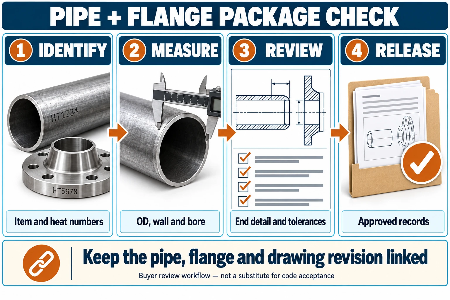
Figure 2. Suggested procurement inspection sequence. Illustrated component identifiers are fictional; they are not shipment records. Project requirements determine the actual checks and acceptance criteria.
| Record or check | What to confirm | Why it matters |
|---|---|---|
| Identification | Item, material and traceability correspond to the order | Prevents use of a visually similar but different component |
| Pipe-end dimensions | OD, wall and relevant end geometry against the specified basis | Catalogue dimensions do not describe every actual end |
| Flange weld end | Bore and end preparation against approved drawing | Confirms the purchased connection detail |
| Fit-up review | Alignment and transition comply with project requirements | Detects discrepancies before welding |
| Inspection document | Required document type and applicable material results | Documents material supply without assuming it contains every extra test |
| Separate dimensional report | Required measurements, locations and acceptance basis | Makes end compatibility reviewable |
| Weld examination | Method, extent, timing and acceptance per the governing plan | Radiography or other examination is a fabrication requirement, not implied by a flange certificate |
| Deviations | Written disposition and re-inspection where needed | Prevents informal changes from becoming accepted design |
EN 10204 provides the inspection-document framework. Specify any additional dimensional, NDT or assembly records independently rather than assuming that a type 3.1 request includes them all. [8]
The connection must meet the applicable drawing and fabrication acceptance requirements. Nominal bore coordination is useful, but actual end dimensions, alignment and any approved transition also matter. A generic article cannot establish a zero-difference rule or a universal allowable mismatch for all projects.
No. Class is interpreted through the flange standard’s pressure–temperature and material requirements. Pipe wall selection requires its own design basis. Coordinate the resulting wall and bore after those requirements have been established. [1]
It must provide enough information to define the connection. Where schedule is used, state it with nominal size and the relevant dimensional basis. A specified wall and approved connection drawing may also be used where applicable. Do not leave the supplier guessing which pipe end the flange must match.
Use an engineered joint detail consistent with the applicable end-preparation and fabrication requirements. Obtain approval for any transition or machining and confirm the remaining wall. Do not adopt an internet angle or workshop practice as the acceptance rule. [2][3]
Select the gasket as part of the complete sealing interface: applicable standard, gasket type, flange facing, size, rating and service requirements. Do not substitute a “larger bore wins” rule for that review. [6]
A coordinated order specifies the pipe, flange weld end and approved joint detail together. Send Forever Steel the pipe schedule and mating-component drawing with the inquiry. Ask for dimensional exceptions and document requirements to be resolved before manufacture, then verify the actual ends before fabrication.
Editorial evidence check: 14 October 2026. Equations and the invented example are explanatory geometry; all production acceptance limits remain subject to the applicable standard, design and approved drawing.