+8615674993216
 sales@forever-steels.com
 English
 العربية

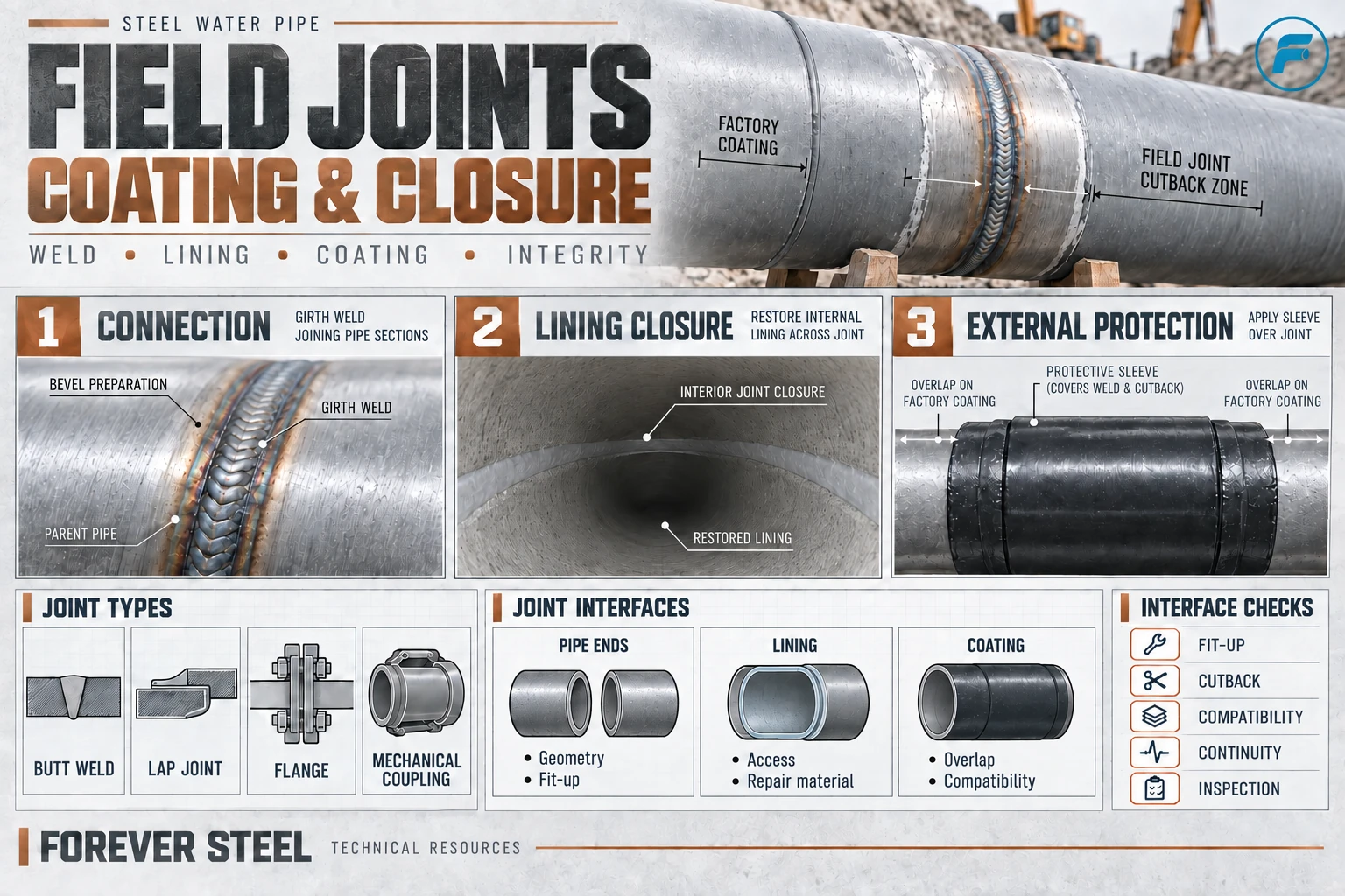
A steel water pipe field joint has to do three things: make the specified connection, complete the internal water-contact protection and restore the external corrosion protection. A watertight gasket or an accepted weld covers only the first. Pipe ends, lining holdbacks and field materials need to be designed as compatible interfaces before the pipe reaches site.
For a project using SSAW steel pipe, send the joint drawing with the inquiry instead of just diameter and wall thickness. The same interface review applies when LSAW steel pipe is selected, because the seam manufacturing route does not decide the field connection.
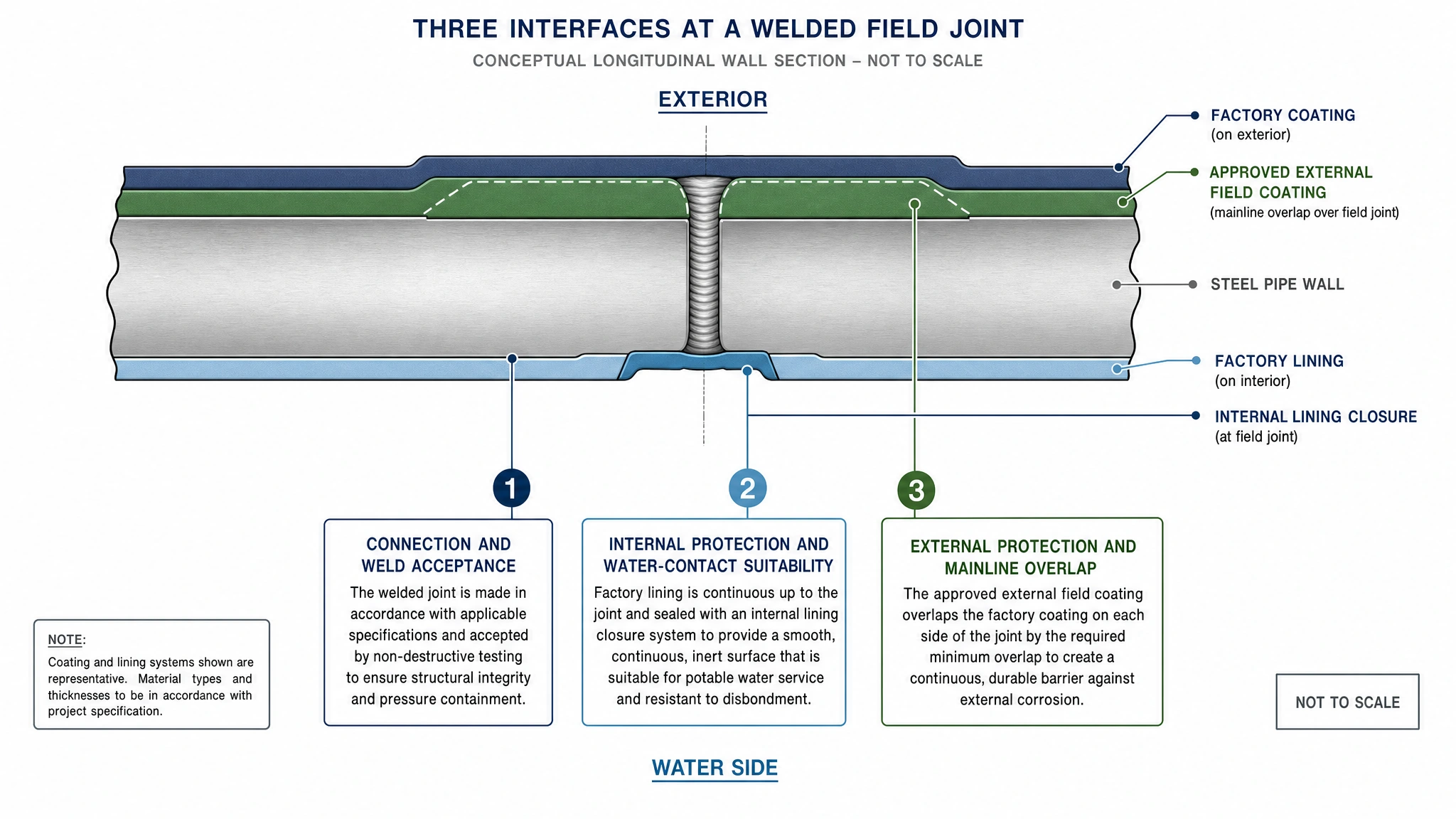
Figure 1. Conceptual interface only, not a fabrication drawing. Internal and external holdbacks are independent dimensions. The approved joint detail sets their lengths, the overlap and the order of completion.
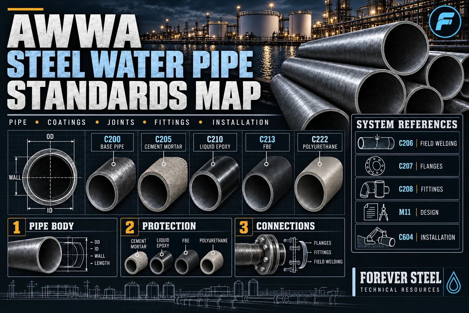
Start with how the connection seals, then ask how axial forces are resisted. A joint that seals against water pressure does not automatically restrain a bend, a valve or an expansion arrangement. For the standards behind these joints, see our AWWA steel water pipe standards map.
|
Joint type |
Sealing or connection principle |
Common decision context |
Field checks and protective closure |
|
Butt weld |
Welded pipe ends |
Restrained welded connection with suitable access |
Fit-up and specified weld examination; restore ID and OD protection |
|
Single or double lap weld |
Welded bell-and-spigot overlap |
Assembly and restraint requirements |
Insertion and overlap; specified weld testing; complete both protective surfaces |
|
Butt strap |
Strap bridges the pipe-end interface |
Approved closure or connection detail |
Strap fit and weld acceptance; protect all exposed joint surfaces |
|
Rolled-groove rubber-gasket bell and spigot |
Compressed gasket in a formed spigot groove |
Non-welded water-pipe assembly |
Gasket seating and insertion; approved internal transition and external closure |
|
Flange |
Bolted, gasketed faces |
Equipment interfaces or accessible connections |
Alignment, gasket and tightening procedure; specified corrosion protection |
|
Mechanical coupling |
Gasketed coupling grips or seals the pipe ends |
Plain-end connections or closure pieces |
End geometry and assembly settings; approved exterior protection |
|
Engineered restrained connection |
Added or integral axial-load transfer |
Thrust or movement control |
Approved restraint details, plus the underlying seal and protective requirements |
|
Expansion joint |
Engineered movement with a sealing arrangement |
Defined thermal or other movement |
Setting, travel, anchors and guides; protection that allows movement |
Restraint is an attribute, not always a joint family of its own. A mechanical coupling may or may not be restrained. A flange, coupling or expansion joint has to be assessed as part of its complete engineered arrangement.
The rolled-groove O-ring bell-and-spigot joint should not be confused with an external grooved mechanical coupling. In the first, the groove holds the gasket on the spigot and the bell compresses it during insertion. Northwest Pipe's joint overview (listed in the references) illustrates this difference and other steel water pipe connections.
The mill supplies the approved bevel, root face, end squareness and dimensional condition. These have to match the qualified field welding procedure, so do not pick a generic bevel angle. Keep the end geometry intact, and keep protective materials out of the defined welding and inspection area.
Ask the manufacturer how circumference, ovality and local end alignment will be checked. Compliance of the pipe body alone does not show that every mating end will assemble within the approved fit-up limits.
The mill needs the bell profile, the spigot geometry, the insertion requirement and whether the joint is single- or double-welded. Check assembly clearance and whether the field crew can reach every specified weld. A drawing that calls for internal work should not be accepted until there is an achievable access and safety plan.
Mark the insertion reference where the approved procedure needs one, and use end protection that keeps the formed geometry intact through shipment and unloading.
Identify the groove or gasket-retaining geometry, the mating bell profile and the approved gasket. State how the dimensions will be inspected, and protect sealing surfaces from distortion, impact and contamination. Never substitute a gasket on nominal diameter alone, since profile, material and service suitability all matter.
Agree who supplies the gaskets, lubricant, installation instructions and replacements. The field team needs the right components and clear insertion criteria, and a note that just says "rubber ring joint" is not enough.
For flanges, coordinate the drilling, face, gasket and bolt arrangement with the mating component. For couplings, coordinate the actual pipe-end diameter, tolerance, surface condition and required insertion depth. If the connection transfers axial force, identify the restraint details and the load path.
Do not add weld beads, coatings or protective wraps in a sealing or gripping area unless the approved connection detail allows it. A small local change can stop the joint from assembling even when the nominal pipe dimensions have not changed.
The mill supplies the approved setting marks, orientation, connection details and installation instructions. Any shipping restraints need to be identified, along with the order in which they are removed. The designer and contractor coordinate anchors, guides and movement allowance. The mill cannot infer these from an expansion joint product name.
Define both terms on a drawing. Suppliers often use "cutback" for an uncoated pipe end and "holdback" for where a lining stops, but the words alone are not a dimensional instruction. Show the internal and external distances from a clearly marked end datum.
To arrive at those distances, work through the connection and closure sequence:
1. Establish the space needed for assembly, welding and the specified examination.
2. Identify where heat or mechanical work could damage the factory lining or coating.
3. Confirm the prepared area and overlap onto sound mainline protection that the field material requires.
4. Check internal access, tools and the method for finishing the water-contact surface.
5. Put the resulting dimensions and tolerances on the approved joint drawing.
A longer cutback is not automatically safer. It adds field work and can make closure harder. A shorter one can leave too little preparation or overlap. Use the approved detail and the application instructions, and do not copy a dimension from another project.
Field welding differs from shop welding in access, fit-up, weather and work sequence. The project has to identify the applicable C206 requirements, the welding procedure and the qualification basis. Check that the procedure covers the actual joint, material and conditions, and that the required personnel qualifications are current and apply.
Plan for wind, rain, condensation and contamination as the procedure requires. Check alignment before welding, and confirm that welding will not damage adjacent protection beyond the allowed repair area. Record any deviation and its approved disposition before coating covers the joint.
The field weld inspection you need depends on the joint and the project specification. A shop seam requirement such as "100% NDT" does not translate into a field-joint inspection plan. Our AWWA C200 manufacturing and inspection records guide covers the factory evidence. Field records need their own joint-level traceability.
Choose the field joint coating against the exact factory system and the installation conditions you expect. Compatibility between material families is only a first screen. Final acceptance needs the named products, preparation, overlap, application limits and inspection procedure. For help with the mainline system, see our guide to lining and coating selection.
|
Factory protection |
Candidate field closure approach |
Approval questions |
|
FBE |
Qualified liquid-applied repair or joint coating; qualified sleeve system |
Does it bond to the prepared FBE and bare steel, and suit the service? |
|
Polyurethane |
Approved liquid-applied closure or compatible sleeve system |
Are recoat preparation, heat limits and overlap defined for this product? |
|
Extruded polyolefin |
Qualified heat-shrink sleeve or another approved joint system |
Are the backing, adhesive or primer and the mainline surface compatible? |
|
Tape system |
Approved field wrap or sleeve arrangement |
Can the specified build-up and transitions be completed without voids? |
|
Cement mortar coating |
Approved mortar closure, with project-specific interface protection |
Are geometry, reinforcement where required, curing and inspection defined? |
These are candidate routes, not approvals. A sleeve manufacturer's preparation and application requirements apply to a named product and its operating envelope. The Canusa XCS product information shows what product-specific installation conditions look like. It does not mean this sleeve suits every water pipeline.
Inspect the bare steel and the adjacent factory protection. Remove contamination and prepare each surface as the approved system requires. Identify the overlap needed onto sound coating, because a sleeve or liquid film should never hide loose edges or a damaged mainline layer.
Record steel temperature and the environmental conditions the application procedure specifies, including dew-point controls where they apply. Heating and cure requirements depend on the product, so do not apply one temperature or cure time across epoxy, polyurethane, tape and heat-shrink systems.
Carry out the specified visual and integrity checks once the material has reached the condition needed for inspection. Where holiday testing applies to the chosen nonconductive barrier, use the approved procedure and settings. Mortar closure has its own acceptance method and should not be electrically tested.
Release the joint only after repairs and reinspection are complete and the system is ready for handling or backfill. If the mainline product is FBE-coated steel pipe, make sure the field material specification goes out with the factory coating requirement and is not left to the installation crew.
Access is a construction and safety decision. It is not simply a pipe-diameter threshold. Entering a pipe can involve confined-space hazards, so competent assessment, isolation, ventilation, monitoring, rescue arrangements and applicable entry controls must be in place before anyone goes in. OSHA's confined-space resources are a useful safety reference, and local requirements govern the work.
For mortar lining, prepare and complete the exposed joint area to the approved detail, keeping the intended transition and curing conditions. For liquid-applied closure, prepare the steel and the existing lining edges, apply the approved water-contact product and confirm cure before return to service. A repair material approved for external use cannot be assumed suitable inside a drinking-water pipe.
Settle internal closure before manufacture. Possible solutions include a qualified remote application and inspection method, or a joint design with an approved protected internal interface. What works depends on the actual pipe, lining and joint geometry.
Ask how the finished internal area will be verified. If the only proposed method needs access that will not exist after assembly, change the plan before delivery. Leaving bare internal steel without an approved design basis is not a closure method.
Map the damage before you repair it. Damage confined to the protective system is one thing. Dents, gouges or weld damage that reach the steel are another. A coating repair must not be used to hide a possible structural defect, so send that condition for engineering disposition.
Identify which coating layers are affected, prepare back to sound material as required and use an approved repair product. Record the material batch, the preparation, the environmental conditions and the reinspection. A repair method accepted in the factory does not make a different field material, or an uncontrolled site process, acceptable.
For factory FBE acceptance, refer to our AWWA C213 inspection guide. Keep that factory record separate from the site damage and repair log.
Do not assume a gasketed or mechanically assembled joint gives dependable electrical continuity. The corrosion-control design determines whether bonding, isolation, test leads or other provisions are needed. An electrically continuous route is not automatically right at every interface.
Where bonding is specified, identify the connection locations and methods before coating or backfill makes them inaccessible. Where an insulating flange is specified, check that adjacent bonding or metallic connections do not defeat its purpose. Record the specified continuity or isolation checks against the joint location and the test-station reference.
Do not copy a standard bonding detail into every order. The owner or corrosion engineer should confirm the intended electrical arrangement and the acceptance criteria.
A factory pipe number identifies a supplied item. A field joint number identifies the installed connection between items. Keep both. A joint map should let an inspector find a repaired connection after the trench has been closed.
|
Record |
Minimum useful identification |
Acceptance question |
|
Joint map |
Joint ID, chainage or location, adjacent pipe IDs |
Can this installed connection be found again? |
|
Assembly record |
Drawing revision, end checks, insertion or fit-up |
Was the approved geometry achieved? |
|
Weld or mechanical acceptance |
Personnel, procedure, specified results |
Was the connection accepted before closure? |
|
Internal closure |
Material, method, access, inspection record |
Is the water-contact interface complete? |
|
External closure |
Batch, preparation, conditions, inspection |
Is protection continuous and accepted? |
|
Electrical interface |
Bonding or isolation requirement and test |
Does the result match the corrosion design? |
|
Repair and release |
Defect location, disposition, recheck, sign-off |
Is the joint released for the next operation? |
Name the party who can release each hold point. Photographs are good evidence, but they do not replace required measurements or an inspection result.
A symptom rarely points to a single cause. Use this table as an investigation and specification checklist, not as a remote diagnosis of an installed pipeline.
|
Observed condition |
Possible issues to investigate |
What to define before ordering |
|
Leakage at a gasketed joint |
Seating, contamination, geometry or movement |
Gasket and end details, assembly limits, test procedure |
|
Coating lift at the overlap |
Surface preparation, contamination or incompatible products |
Named system and approved transition preparation |
|
Voids or bridging under a sleeve |
Profile, heating or application technique |
Geometry limits and qualified application method |
|
Damaged lining beside a weld |
Thermal effects, inadequate holdback or closure defects |
ID holdback and inspection after welding |
|
Cracked or loose mortar closure |
Preparation, movement, curing or damage |
Closure detail, curing and repair acceptance |
|
Unexpected electrical test result |
Missing bond, unintended contact or isolation fault |
Electrical interface drawing and test requirements |
For every inspection photograph, record the joint ID, date, defect location and, where useful, a scale. In the report, keep the visible condition apart from the suspected cause, and keep photographs of the finished repair with its acceptance record.
Fill in one sheet for each distinct joint arrangement. Refer to drawings and procedures instead of trying to fit every technical requirement into the form. "Not applicable" should be an explicit decision, not a blank field.
|
Field |
Information to enter |
|
Project and location |
Project name; service; line or section; joint type reference |
|
Pipe identification |
OD; wall; length; material; manufacturing specification |
|
Joint drawing |
Drawing number; revision; connection and restraint details |
|
End dimensions |
Bevel or bell/spigot geometry; tolerances; inspection method |
|
Internal protection |
Lining product; specification; holdback; closure method |
|
External protection |
Mainline system; cutback; field product; required overlap |
|
Access and safety |
Internal access or remote method; responsible contractor |
|
Welding or assembly |
Procedure; qualifications; installation limits |
|
Electrical interface |
Bonding or isolation detail; test-point reference |
|
Inspection |
Connection, internal and external checks; hold points |
|
Supply boundary |
Mill-supplied and contractor-supplied materials and services |
|
Approval and release |
Owner/designer; manufacturer; contractor; inspector; revision date |
Agree the form before the pipe-end and coating details are frozen. A change to a joint detail can affect the pipe factory, the coating applicator and the site contractor all at once.
Not necessarily. What matters is an approved, compatible system, with evidence for the actual products and conditions. The same brand does not prove compatibility by itself, and mixing brands needs a clear approval basis.
It can. The gasket seals the connection, while external corrosion protection is a separate requirement. The approved design decides how the outside of the joint and the internal lining transition are completed.
The approved joint design and closure process determine it, with input from the manufacturer, the coating supplier and the contractor. The owner or designer approves the interface under the project's responsibility structure.
No. A corrosion-protection sleeve is not the structural connection. It protects an accepted joint, unless a separately engineered product is explicitly designed and approved to do something more.
AWWA Steel Water Pipe Standards Map
AWWA C200 submittal register and inspection records
AWWA C213 FBE water pipe RFQ and inspection guide
FBE and abrasion-resistant overcoats for HDD crossings
AWWA official standards directory - field welding, couplings and joint specification identifiers.
Northwest Pipe steel water pipe joint overview - joint mechanisms and terminology.
Performance of gasket joints in steel pressure pipes - manufacturer-authored technical paper; historical context, not current project acceptance limits.
Canusa XCS heat-shrink sleeve system - product-specific application requirements.
OSHA confined space resources - entry hazards and applicable work controls.
NSF ANSI CAN 61 testing and certification - water-contact health-effects scope.