+8615674993216
 sales@forever-steels.com

 English
 العربية







A seamless pipe can contain surface folds, scabs, internal grooves or unacceptable wall variation despite having no longitudinal weld. Visual examination, dimensional measurement and specified nondestructive testing answer different questions. Acceptance requires the ordered product standard, project limits and traceable inspection results; a clean-looking bore or a statement of 100% NDT is insufficient by itself.
For buyers, the immediate task is to identify the pipe, locate the indication and establish which requirement governs it. Do not approve grinding from a photograph or reject every rolling mark as a crack. Record the evidence needed to distinguish an appearance issue, a dimensional nonconformance and a relevant material discontinuity. This guide concerns newly manufactured seamless steel pipe, not remaining-life assessment of pipe already in service.
The absence of a longitudinal weld removes one manufacturing feature, but it does not remove the need for control during billet preparation, heating, piercing, rolling, cold working and treatment. Defects or indications can occur at the outside surface, bore or within the wall. Their direction and geometry affect how they should be investigated.
Terminology must be tied to observations. A supplier may use fold, lap, seam, scab or groove differently from another supplier. Rather than debating the label first, record the axial location, circumferential position, length, width, depth where measured, and the examination method. A manufacturer or metallurgical investigation can then evaluate the likely origin without turning a visual description into a proven cause.
For weld-specific mechanisms such as lack of fusion or slag inclusion, use the separate weld defect investigation guide. A seamless pipe body requires its own inspection scope; copying a weld inspection plan and changing the product name can leave relevant regions or orientations unexamined.
A lap is associated with folded-over material and can produce a line or overlap at a surface. An internal fold occurs at the bore and may be less accessible to direct viewing. A scab is a local surface feature involving attached or rolled-in material; it should not be confused with loose oxide scale solely because both can look raised.
A scratch or groove describes a depression or mark rather than establishing its manufacturing mechanism. Tool contact, handling or another operation may be involved. Rounded internal grooves also create a detection challenge: Evident describes a rounded-bottom internal flaw in seamless tube for which reflected ultrasonic energy is dispersed by its shape. A rounded appearance is therefore not evidence that the feature is harmless or easy to detect. [1]
Table 1. Observed features and the first evidence to collect.
|
Observed feature |
First evidence to collect |
Decision to avoid making too early |
|
Outside lap or folded line |
Close view, extent, orientation and suitable follow-up examination |
Treating a tight line as a harmless scratch |
|
Raised scab or rolled-in patch |
Whether the feature is scale or metal, affected area and underlying surface |
Approving removal without checking the material below it |
|
Internal fold or bore groove |
Internal visual evidence, axial position and a suitable detection or sizing method |
Assuming pipe-end viewing represents the entire bore |
|
Scratch gouge or handling depression |
Geometry, measured remaining wall and any associated cracking |
Accepting solely because nominal wall was originally generous |
|
Uneven wall or eccentric section |
Circumferential and longitudinal wall measurements with defined calculation |
Replacing a local minimum with the average wall |
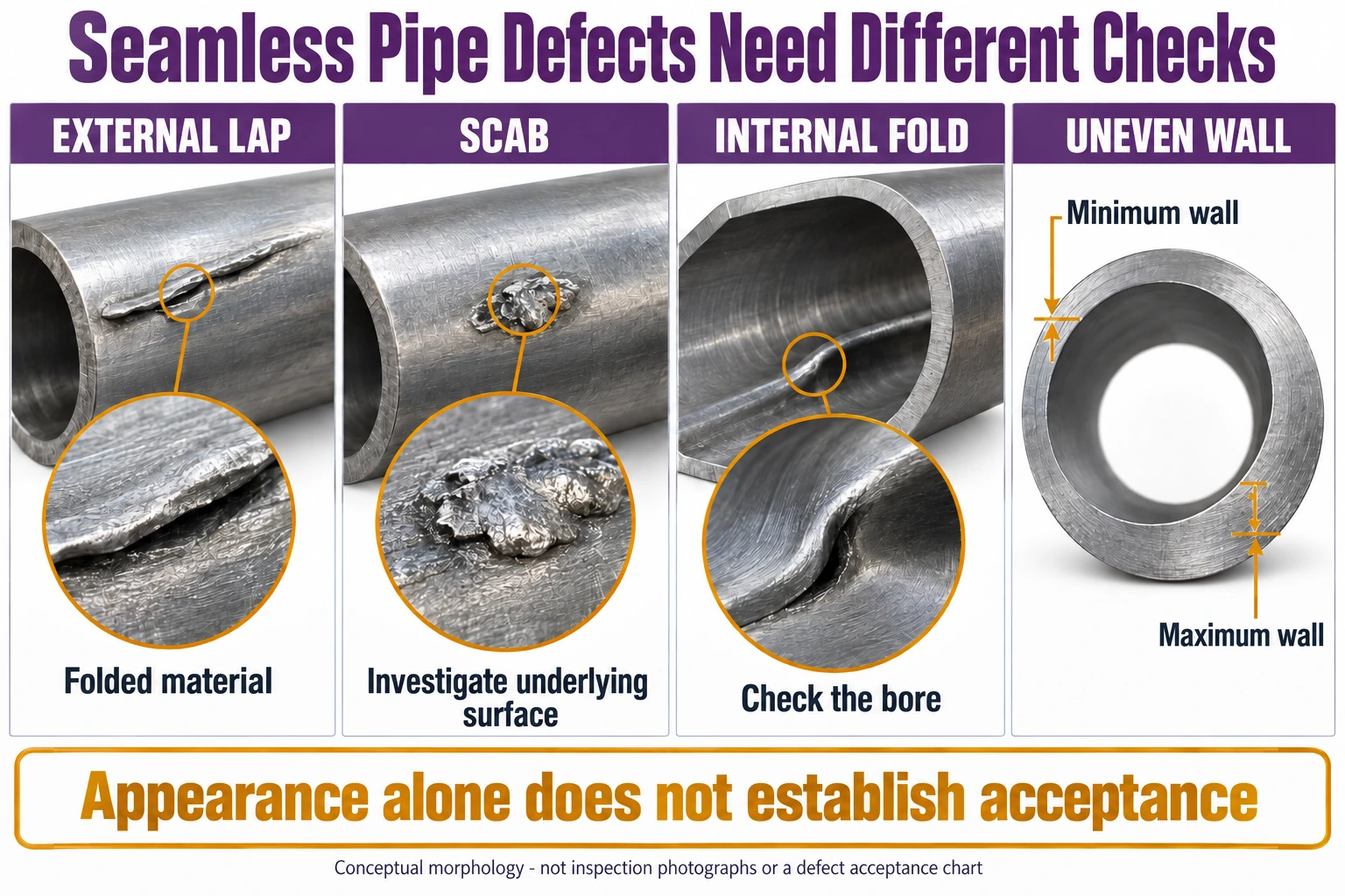
Figure 1. Conceptual defect appearances and wall geometry. These original illustrations are not inspection photographs, metallographic evidence or acceptance examples. Similar-looking features can require different investigations.
Wall variation is the difference among measured thicknesses. Eccentricity describes a geometric relationship that requires a defined measurement and reporting convention. In real pipe, ovality, local thinning, surface condition and longitudinal variation can all influence the readings. Two diameters measured at one end do not provide a full map of the wall.
Consider an illustrative circular section with a maximum measured wall of 10.7 mm and a minimum of 9.3 mm. The range is 1.4 mm and their mean is 10.0 mm. Dividing the range by that mean gives 14%; dividing half the range by the same mean gives 7%. A report containing only the word eccentricity and a percentage is ambiguous unless the formula and measuring basis are stated.
Table 2. Wall variation calculations using stated definitions.
|
Reported quantity in the example |
Calculation |
Result |
|
Maximum minus minimum wall |
10.7 − 9.3 |
1.4 mm |
|
Mean of the two extreme readings |
(10.7 + 9.3) / 2 |
10.0 mm |
|
Range divided by that mean |
1.4 / 10.0 × 100 |
14% |
|
Half-range divided by that mean |
0.7 / 10.0 × 100 |
7% |
These are reporting illustrations, not two competing universal acceptance standards. Use the definition required by the order, product standard or drawing. If the requirement is minimum local wall, compare the appropriate verified minimum to that limit regardless of whether the wall-variation percentage appears small.
For machining stock, the importance of bore position depends on the datum and finished part. The existing A519 Grade 1026 functional tolerance guide addresses that dimensional interaction. For pressure pipe, geometry and product acceptance must remain connected to the governing specification and design requirements.
Visual examination, dimensional measurement and specified nondestructive testing answer different questions. The sections below cover ultrasonic, eddy current and magnetic flux leakage methods, then compare them in one table.
Ultrasonic testing uses sound propagation and reflected signals. A flaw-detection arrangement is selected around the target discontinuities and their orientations. A wall-thickness arrangement is selected to determine thickness. Sharing the label UT does not make their outputs interchangeable or prove that both tasks were completed.
ISO 10893-10:2011 describes automated full-peripheral ultrasonic examination for longitudinal and/or transverse imperfections, using conventional or phased-array shear-wave techniques. Its public scope gives an OD of at least 10 mm and normally an OD-to-wall ratio of at least 5. Its 2020 amendment addresses test frequency and acceptance criteria. Those scope details must not be converted into a universal UT acceptance rule for every seamless product. [2][3]
ISO 10893-12:2011 separately concerns automated ultrasonic thickness measurement. Its referenced amendment also needs consideration when establishing the ordered examination basis. A thickness map can help identify local wall variation, but it is not automatically a qualified search for every crack-like discontinuity. Ask which channels, orientations, reference features and acceptance rules were used for each purpose. [4]
Oblique indications deserve explicit attention where relevant. A plan set up only for selected longitudinal and transverse reflectors should not be described as proving detection at every possible angle. Evident identifies oblique-angle coverage as a specific challenge in seamless tube examination. The correct response is an agreed capability and procedure, not an unsupported claim that more probes eliminate every limitation. [5]
Eddy current testing responds to changes in electromagnetic interaction with electrically conductive material. Coil or probe arrangement, frequency, material condition, dimensions and the target discontinuity influence the examination. A supplier should state what its particular system is intended to detect and which procedure or product rules control the result.
The public scope of ISO 10893-2:2011 covers automated eddy current examination of seamless and certain welded tubes for imperfections and identifies a minimum OD of 4 mm. That is a scope statement, not a guarantee that every feature in every 4 mm or larger tube will be detected. Acceptance levels, reference pieces, material suitability and the applicable amendment still require review. [6]
Magnetic flux leakage testing magnetizes suitable material and detects leakage associated with discontinuities. ISO 10893-3:2011 specifically concerns ferromagnetic steel tubes and longitudinal and/or transverse imperfections. It must not be presented as a default method for all stainless grades. Material magnetic behavior, magnetization direction, sensors and calibration determine the relevant capability. [7]
Table 3. Inspection methods and the questions they answer.
|
Examination |
Useful question it can address |
Requirement to define |
|
Visual examination |
What accessible surface feature is present |
Surface preparation, access, lighting and recording method |
|
UT flaw detection |
Are relevant reflectors detected under the qualified procedure |
Orientations, calibration, coverage and acceptance level |
|
UT thickness measurement |
What wall thickness exists in the examined area |
Scan coverage, measurement settings and local minimum reporting |
|
Eddy current testing |
Does the selected conductive-tube system detect the target response |
Material setup, reference features, sensitivity and end limitations |
|
Magnetic flux leakage |
Are target discontinuities detected in suitable ferromagnetic tube |
Magnetization, direction, reference standard and acceptance basis |
|
Hydrostatic test |
Does the pipe withstand the specified pressure test conditions |
Pressure, duration, setup and product identification |
Hydrostatic testing belongs in the inspection matrix, but it does not provide a complete morphological classification of every fold, scab or local wall condition. Product specifications may provide defined testing options. The purchaser should establish the permitted selection without assuming that a pass in one examination proves the result of another.
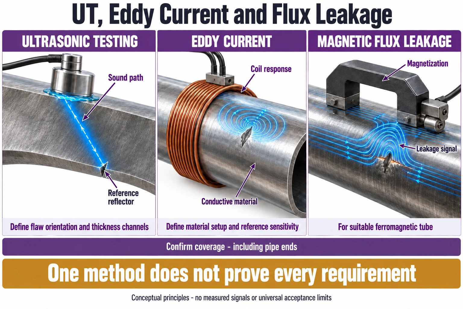
Figure 2. Simplified examination principles. Each method needs its own material suitability, reference standard, coverage and acceptance basis. The acoustic and electromagnetic paths are conceptual, not measured inspection data.
The percentage needs a denominator. It might refer to all pieces, a specified examination length or a particular surface and orientation. A declaration that every pipe entered the line does not establish that every required region was examined at the agreed sensitivity.
For a transparent length-only example, assume a 12,000 mm pipe and a system leaving 200 mm unexamined at each end. The main system covers 11,600 mm, or 96.67% of length. This does not calculate full surface-area coverage or detection probability. It simply shows why end treatment needs a separate answer even when all pieces passed through the equipment.
Ask whether the ends are cropped, separately examined or addressed by another approved method, and how the final retained pipe is identified. Evident offers tube-end systems specifically because conventional automated arrangements can leave untested end lengths. The actual limitation depends on the equipment and configuration; 200 mm is an assumed teaching value, not its published universal limit. [8]
Reference sensitivity also requires careful wording. If an illustrative procedure used a reference notch equal to 5% of a 10.0 mm nominal wall, the reference depth would be 0.50 mm. That arithmetic does not mean every natural discontinuity deeper than 0.50 mm is detectable, or every shallower one acceptable. Signal response depends on more than depth, and contractual rules govern disposition.
Before removing material, identify the indication and confirm whether the product specification and project allow that disposition. Establish the boundary, material-removal method, required surface blending and follow-up examination. Do not turn an uninvestigated fold into an apparently clean depression and then lose the original evidence.
The following example uses an assumed 9.00 mm local minimum specified by a hypothetical purchase order. It is not an ASTM, API or EN tolerance. The starting local measurement is 9.65 mm. Removing 0.45 mm gives an estimated 9.20 mm; removing 0.80 mm gives 8.85 mm. Actual release requires the final measured wall and all other applicable checks.
Table 4. Illustrative remaining-wall calculation after removal.
|
Illustrative correction |
Estimated remaining wall |
Comparison with assumed 9.00 mm minimum |
|
Remove 0.45 mm from a 9.65 mm local wall |
9.20 mm |
0.20 mm above the assumed minimum before measurement and other checks |
|
Remove 0.80 mm from the same local wall |
8.85 mm |
0.15 mm below the assumed minimum |
A gauge displaying 0.01 mm increments does not automatically have 0.01 mm accuracy. Surface roughness, coupling, calibration, material condition and instrument performance can affect the result. Where a reading is close to the limit, use the agreed measurement and decision rule; do not invent a margin or round a failing value into compliance.
Tenaris's hydraulic-cylinder tube brochure provides a product-specific example of segregation, cropping, dressing or rejection, followed by reinspection and dimensional conformity. This supports the structure of a controlled repair decision. Its grade-specific reference levels are not general acceptance percentages for A106, A335 or API 5L pipe. [9]
The report should allow a buyer to connect the original observation, investigation, disposition and final release. A certificate stating passed is difficult to audit without the underlying requirement and pipe identity. Attach a defect map and preserve the relationship between the original and final records.
Table 5. Fields for an actionable defect and inspection report.
|
Record field |
Information to retain |
|
Identity and requirement |
PO line, product standard and edition, grade, heat, pipe or bundle identity |
|
Location and appearance |
Axial distance, clock position, accessible surface, dimensions and photographs |
|
Examination basis |
Method, procedure, reference standard, calibration and operator authorization |
|
Result and limit |
Relevant indication, measured wall or other output, acceptance criterion and units |
|
Disposition |
Hold, additional examination, permitted dressing, cropping, rejection or approved concession |
|
Final verification |
Reinspection results, final dimensions and length, identification transfer and release authority |
A cropped pipe may comply with the surface requirement but become too short. A dressed surface may retain sufficient wall but need additional examination. A technically acceptable concession may still require purchaser approval. Resolve these consequences before the affected quantity disappears into a bundle with the rest of the order.
Tell the supplier whether the service or downstream fabrication imposes requirements beyond the basic product standard. Machining allowance, cyclic service, close bore clearance, coating preparation and pipe-end fit can alter what evidence the project needs. State those requirements in measurable terms rather than requesting defect-free material without a defined inspection basis.
For ASTM A106 seamless pipe, alloy seamless pipe or another family, request the actual NDE scope, dimensional report, repair restrictions and release records at inquiry. The supplier should identify deviations and any capability that needs separate confirmation for the requested grade, OD, wall and length.
No. It can be a surface mark, groove, fold or another feature. Its appearance alone does not establish mechanism, depth or acceptability. Record the location and geometry, then investigate with methods suitable for the suspected condition and applicable requirement.
No. An average can hide a local thin region. Use the required measurement coverage and the correct local or other acceptance basis. Circumferential wall variation and geometric eccentricity also need their stated reporting definitions.
Only where the governing specification and approved purchase requirements permit the proposed selection and its demonstrated capability. The methods do not have identical responses, coverage or material limitations. Resolve the target imperfections and reporting requirements before approving a substitution.
Do not infer permission from repair practices for welded pipe. The applicable product specification and project determine whether a proposed repair is permitted, under which conditions, and with which procedure and approval. If it is not permitted, a repair WPS cannot create that permission.
Treat surface appearance, discontinuity detection, wall geometry and final quantity as connected acceptance decisions. Send Forever Steel the ordered product and service requirements with any defect photographs or reports, retaining pipe identity and measurement details. A complete evidence package supports a defensible disposition; an attractive surface after unrecorded removal does not.
• Steel Pipe Inspection Checklist Before Shipment
• How to Read a Steel Pipe MTC
• Passed 100% NDT? What UT and RT Actually Prove About the Weld
• Seamless Steel Pipe Manufacturing Process: From Billet to Finished Pipe
• Seamless Pipe Workshop: Size Ranges and Inspection Framework
• ASTM A335 Wall Thickness Tolerance: Weight, Bore and Invoice
[1] Evident Detecting Rounded Shape Internal Defects in Pipes. Seamless-tube internal groove detection context.
[2] ISO 10893-10:2011. Public scope of automated full-peripheral UT for longitudinal and/or transverse imperfections.
[3] ISO 10893-10:2011 Amendment 1:2020. Amendment concerning test frequency and acceptance criteria.
[4] ISO 10893-12:2011. Automated ultrasonic thickness measurement scope; review applicable amendments with the ordered examination basis.
[5] Evident Calibration of an Entire Range of Oblique Defects. Orientation and calibration coverage.
[6] ISO 10893-2:2011. Public scope of automated eddy current tube examination; amendment applicable as specified.
[7] ISO 10893-3:2011. Magnetic flux leakage examination of ferromagnetic tubes; review applicable amendments.
[8] Evident Tube End Inspection System. Manufacturer explanation of automated-system end limitations.
[9] Tenaris Seamless Tubes for Hydraulic Cylinder Applications. Product-specific NDT and dressed-tube reinspection example.