+8615674993216
 sales@forever-steels.com
 English
 العربية





Make sure the thickness you order is the thickness being applied and measured.
Customers have told us about pipe paint peeling or cracking after the pipes had been stored for some time.A thickness reading alone cannot explain why that happened or show how long the coating will protect the pipe.But it gives us a practical place to start: what coating was ordered, and what thickness was actually measured?
For coated steel pipes, even a small wording difference can complicate that check.10 mils is exactly 254 microns—not 250 microns.One mil equals 25.4 µm, so divide microns by 25.4 to get mils, or multiply mils by 25.4 to get microns. [1, 2] Keep “nominal” or “minimum” attached to the requirement when you convert it.
The next question is what the reading includes. Was it taken while the paint was wet or after it dried? Does it measure paint alone, or paint plus the zinc underneath? Sorting out those points makes the order, application target and inspection report easier to compare. Investigating peeling or cracking then requires the coating and storage records as well—not just another conversion.
Jump to: Order/report mismatch | Conversion chart | WFT target | Zinc and paint | FAQ
|
What the documents say |
What needs to be checked |
Useful calculation |
|
250 µm on the order; 10 mils on the quotation |
Nominal target or a strict minimum? |
10 mils = 254 µm |
|
250 µm dry film required; 250 µm measured wet |
Wet and dry film are different quantities |
Use the mixed coating's volume solids |
|
Paint thickness required over galvanized steel |
Does the gauge include the zinc layer? |
Identify the measurement method before comparing |
|
Average thickness is acceptable; some readings are low |
Which readings, spots or areas control acceptance? |
Apply the specified inspection plan |
|
Coating specified in g/m² |
Coating mass per area is not a length unit |
Material density and the reporting basis are needed |
Surface profile describes the prepared substrate's peak-to-valley texture; DFT describes the applied dry coating. They are separate measurements. [9] An illustrative 60 µm profile equals about 2.362 mils, but it is not 2.362 mils of paint and cannot be added to the paint thickness as another coating layer. Keep profile and DFT in separate report fields.
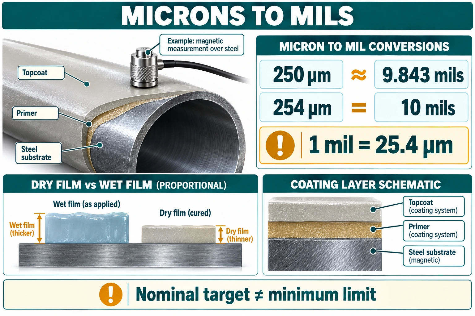
Figure 1. Keep the original requirement when converting. Rounding a target does not redefine an acceptance limit.
The values below are dimensional conversions, not recommended coating thicknesses. The required thickness depends on the specified product, system and service.
|
Microns (µm) |
Mils, rounded |
millimeters (mm) |
|
25.4 |
1.000 |
0.0254 |
|
50 |
1.969 |
0.05 |
|
75 |
2.953 |
0.075 |
|
100 |
3.937 |
0.1 |
|
125 |
4.921 |
0.125 |
|
150 |
5.906 |
0.15 |
|
200 |
7.874 |
0.2 |
|
250 |
9.843 |
0.25 |
|
254 |
10.000 |
0.254 |
|
300 |
11.811 |
0.3 |
|
350 |
13.780 |
0.35 |
|
400 |
15.748 |
0.4 |
|
500 |
19.685 |
0.5 |
|
750 |
29.528 |
0.75 |
|
1000 |
39.370 |
1 |
|
2000 |
78.740 |
2 |
|
3000 |
118.110 |
3 |
Conversion formulas
· Mils = microns ÷ 25.4.
· Microns = mils × 25.4.
· millimeters = microns ÷ 1,000.
· Inches = mils ÷ 1,000.
For example, 8–12 mils converts to203.2–304.8 µm. Preserve those endpoints in a comparison worksheet. Changing the range to 200–300 µm would create a different range, even though it might look more convenient on an inspection form.
Multiply mils by 25.4 to obtain microns. These are exact dimensional conversions for the stated inputs, not recommended coating thicknesses. [1, 2]
|
Mils |
Microns (µm) |
Millimeters (mm) |
|
0.5 |
12.70 |
0.01270 |
|
1 |
25.4 |
0.0254 |
|
2 |
50.8 |
0.0508 |
|
3 |
76.2 |
0.0762 |
|
4 |
101.6 |
0.1016 |
|
5 |
127.0 |
0.1270 |
|
6 |
152.4 |
0.1524 |
|
8 |
203.2 |
0.2032 |
|
10 |
254.0 |
0.2540 |
|
12 |
304.8 |
0.3048 |
|
15 |
381.0 |
0.3810 |
|
20 |
508.0 |
0.5080 |
|
30 |
762.0 |
0.7620 |
|
40 |
1016.0 |
1.0160 |
|
80 |
2032.0 |
2.0320 |
|
120 |
3048.0 |
3.0480 |
8 mils = 203.2 µm; 10 mils = 254 µm; 12 mils = 304.8 µm.Keep the original nominal, minimum or range wording when transferring these values to an inspection sheet.
Numerically, no:250 µm is 4 µm below 10 mils. However, this numerical difference alone is not a complete inspection decision. The contract may specify nominal thickness, a minimum at defined measurement locations, a permitted range, or an averaging procedure. Gauge uncertainty and the agreed acceptance method also matter.
|
Original wording |
Converted wording |
What must stay unchanged |
|
Nominal DFT: 10 mils |
Nominal DFT: 254 µm |
The word “nominal” |
|
Minimum DFT: 10 mils |
Minimum DFT: 254 µm |
The specified minimum and its measurement basis |
|
DFT range: 8–12 mils |
DFT range: 203.2–304.8 µm |
Both endpoints and the inspection rule |
DFT means dry film thickness. Avoid a purchase-order line such as “250 µm / 10 mils minimum” unless the documents explain which value governs. A clearer line preserves the original requirement and marks the other number as a converted reference.
If an inspection record says 250 µm against a 10 mil minimum, ask for the original readings, gauge verification record and applicable acceptance clause. Do not resolve the discrepancy by rounding 9.843 up to 10.
A liquid coating loses volatile material as it dries. Its wet film thickness (WFT) is therefore different from its dry film thickness. The calculation usesvolume solids, not weight solids. Obtain the value for the mixed coating from the applicable technical data sheet; do not substitute the solids value of an individual component. [3, 4]
Theoretical WFT = target DFT ÷ volume-solids fraction.
Assume a liquid coating has 65% volume solids and the specified dry film is 250 µm:
250 ÷ 0.65 =384.62 µm WFT, approximately15.142 mils.
A wet reading of 250 µm would theoretically produce only 162.5 µm dry film at the same solids content. Checking the unit without checking the film condition would miss that difference.
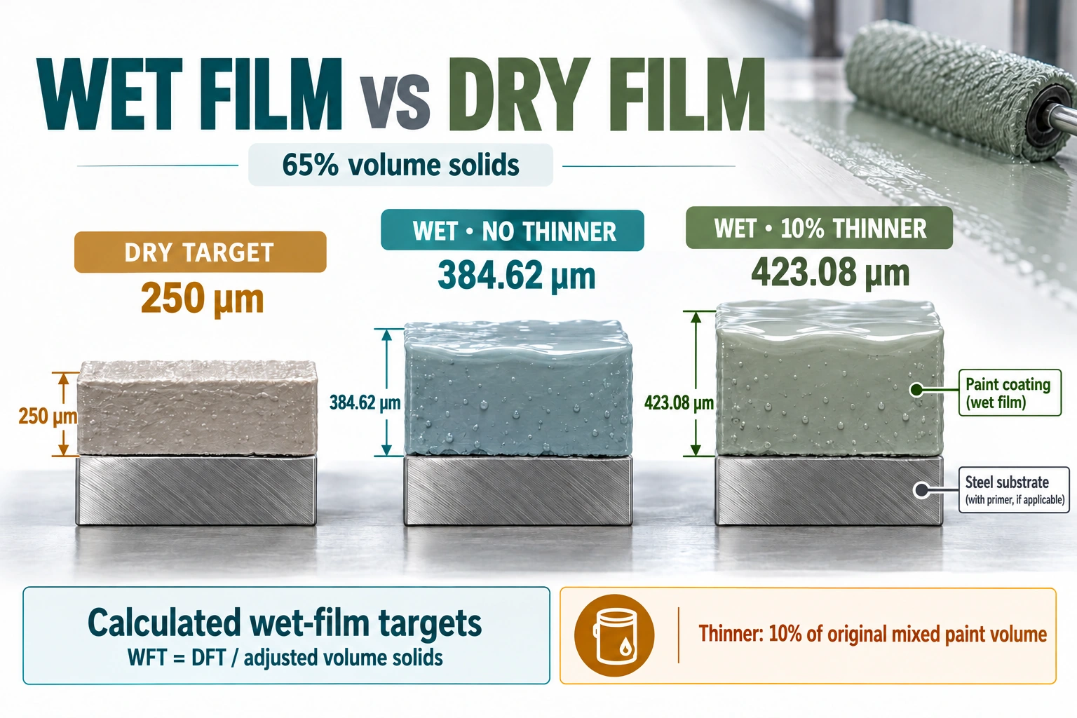
Figure 2. Illustrative liquid-coating calculation. The product data sheet determines permitted thinning and the thickness range per coat.
Suppose the manufacturer permits thinner and the applicator adds a volume equal to10% of the original mixed paint volume. The effective solids fraction becomes 0.65 ÷ 1.10, or approximately 0.5909. The theoretical wet film needed for 250 µm dry film rises to:
250 × 1.10 ÷ 0.65 =423.08 µm WFT, approximately16.657 mils.
|
Illustrative application |
Theoretical WFT for 250 µm DFT |
Solids fraction used |
|
Mixed coating, no added thinner |
384.62 µm |
0.65 |
|
Thinner added at 10% of mixed paint volume |
423.08 µm |
0.65 ÷ 1.10 |
|
Same 384.62 µm WFT retained after that thinning |
Produces about 227.27 µm DFT |
0.65 ÷ 1.10 |
The last row explains how an unchanged wet-film target can lead to a thinner dry coating. Record the thinning basis: “10% of paint volume” is different from “10% of the final mixture.” This example is not a recommendation to thin a product or apply the full thickness in one coat. [3, 4]
These are planning calculations. Actual dry-film readings still need to be checked after the specified drying or curing stage. For powder coatings such as FBE, do not apply a liquid-coating volume-solids calculation to uncured powder thickness; the measurement and cure relationship require the relevant powder-coating method. [5]
Paint over galvanized steel creates a measurement question that unit conversion cannot answer. A conventional magnetic coating gauge may measure the combined nonmagnetic layers above the steel, including both zinc and paint. DeFelsko describes staged measurements and instruments designed to distinguish the layers in a duplex system. [6]
For an illustrative location with 70 µm of zinc and 110 µm of paint, the combined thickness is 180 µm. Calling the total “180 µm paint DFT” would overstate the paint layer.
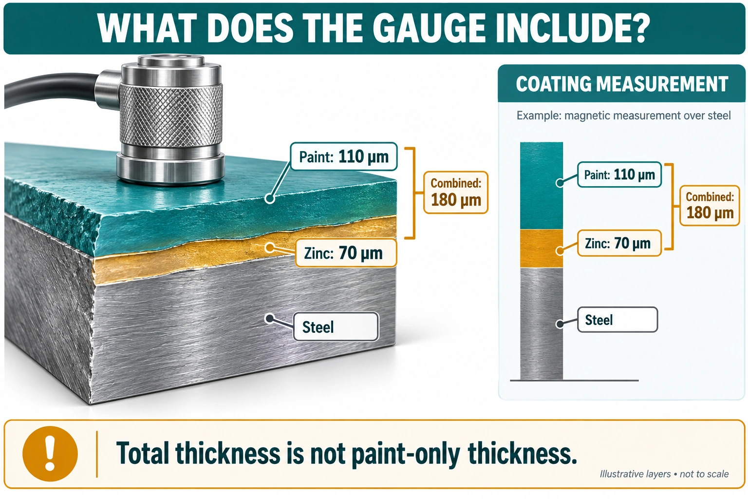
Figure 3. A combined reading and a paint-only reading answer different questions. Layer dimensions are illustrative.
Subtracting a zinc reading taken somewhere else can also give a misleading paint thickness if the zinc varies between locations. Agree on the instrument and measurement procedure before production, especially where the specification sets separate requirements for the zinc and paint.
Consider three illustrative readings: 180, 250 and 320 µm. Their arithmetic average is 250 µm. That average does not mean every location has 250 µm, and it does not establish whether the inspected area passes.
Inspection procedures distinguish individual gauge readings, spot measurements and area measurements. Where SSPC-PA 2 is specified, the applicable procedure and agreed restriction level need to be identified. Do not invent a universal “±20%” allowance or apply an averaging rule simply because a gauge can calculate it. [7]
Check the measurement setup before calling this a unit error. DeFelsko identifies curvature, roughness and substrate properties as factors that can require application-specific adjustment. Verification on a flat standard does not by itself reproduce the pipe surface. [10]
Record pipe diameter, measurement location, probe identity and the verification/adjustment method. Follow the instrument's procedure for the actual substrate and geometry. Do not invent a universal correction factor or automatically subtract blast-profile height from every reading.
Keep the original readings, sampling locations and instrument verification records with the specified DFT range. Identify repair areas separately where required.
Thickness also connects the inspection requirement to a quotation. For a straight pipe, the external cylindrical area is π × outside diameter × coated length. When diameter and length are in meters, the result is in square meters.
Consider 100 pipes, each with an outside diameter of 323.9 mm and a coated length of 12 m. Assume full external cylindrical coverage, excluding ends, cutbacks and internal surfaces. At 250 µm DFT and 65% volume solids:
|
Calculation |
Basis |
Approximate result |
|
External area |
π × 0.3239 × 12 × 100 |
1,221.07 m² |
|
Dry coating volume |
Area × 250 ÷ 1,000 |
305.27 liters |
|
Mixed paint before thinner |
Dry volume ÷ 0.65 |
469.64 liters |
This theoretical quantity excludes application losses, surface-profile effects and retained material; it is not a purchasing allowance or coverage guarantee. Adding thinner increases liquid volume, not coating solids.
A compliant thickness reading alone does not establish adhesion, cure or service suitability; excessive build can cause application problems such as solvent entrapment. [3] For the separate checks required by the purchase specification, see pipe coating inspection before shipment.
For example, “250 µm epoxy” leaves several questions unanswered: external body or internal lining; a single coat or total system; nominal or minimum; and which areas are excluded or repaired. Identify pipe-body coating, cutbacks and field-joint or repair areas separately where the order distinguishes them. Do not assume one thickness requirement covers them all.
|
Field |
Information to provide |
Dispute it helps avoid |
|
Coating system |
Product or approved system; substrate; coated surfaces |
Comparing different protective systems |
|
Thickness |
Original unit; nominal/minimum/range; per coat or total |
Rounding and layer ambiguity |
|
Application basis |
Applicable data sheet; permitted thinning; coat sequence |
Using the wrong wet-film target |
|
Inspection |
Method; sampling and acceptance requirements |
Treating a single reading as a complete inspection |
|
Traceability |
Pipe or batch identity; measurement and repair records |
Results that cannot be matched to the shipment |
A useful clarification to a supplier is: “Please retain the specified thickness in its original unit, identify whether the reported value is paint-only or total-system DFT, and provide the inspection basis used for acceptance.”
No. A total reading does not allocate thickness to each coat. Where individual coats have specified limits, retain the required stage records or use the agreed method. Even an instrument that separates zinc from paint may report multiple paint coats together. [11]
No. Confirming DFT resolves only the thickness check. Preserve the coating identification, application and cure records, storage conditions and defect photographs for a separate investigation. Neither a compliant converted value nor a thicker film establishes the cause or warranty responsibility.
1 mil equals exactly 25.4 microns (µm), or 0.0254 mm. Multiply mils by 25.4 to obtain microns. [1, 2]
No. One mil is 0.001 inch, exactly 0.0254 mm or 25.4 µm. One millimeter is approximately 39.370 mils.
Microns specify only the unit of length. The document must identify WFT or DFT. The same numerical value represents different coating conditions when used for wet and dry film.
Not as a simple unit conversion. Mass per area and thickness are different quantities. A calculation requires the coating density and a clear basis for the reported area and layers. For galvanized pipe, also check how the applicable specification reports coating mass or thickness.
Yes. On galvanized steel, a conventional magnetic gauge may include zinc and paint in the total nonmagnetic thickness. Use the specified procedure or an appropriate instrument to establish the paint-only result. [6]
No. A wet-film calculation helps control application. The final dry-film result still needs verification using the specified inspection method and acceptance requirements.
Convert µm and mils with the exact factor of 25.4, then check what the thickness describes: wet or dry, one layer or the whole system, nominal or minimum. Preserving those distinctions makes coating quotations, application targets and inspection records comparable.
For a coated-pipe inquiry, include the pipe size, coating system, required dry-film thickness or range, and inspection requirements. State whether the thickness applies to one coat or the full system.
· Galvanized pipe coating thickness: g/m² and µm — use the correct basis when the zinc coating is specified by mass per area.
· FBE powder coating: film formation and application limits — distinguish powder-coating control from liquid-paint WFT calculations.
1. NIST — Guide to the SI, Appendix B.9: conversion factors.
2. BryCoat — Coating thickness conversion table.
3. KTA — Calculating wet film thickness.
4. DeFelsko — How to measure wet film paint thickness before cure.
5. DeFelsko — Coating thickness measurement instruments.
6. DeFelsko — Duplex coating system thickness measurement.
7. DeFelsko — Using SSPC-PA 2 mode for coating thickness measurements.
8. DeFelsko — How to ensure accurate dry film thickness readings.
9. DeFelsko — Surface profile measurement — substrate profile is a separate measurement from coating thickness.
10. DeFelsko — Calibration, verification and adjustment — measurement setup for substrate geometry and roughness.
11. KTA — Inspection of galvanizing cleaning and coating — duplex and multiple-coat measurement limitations.