+8615674993216
 sales@forever-steels.com
 English
 العربية

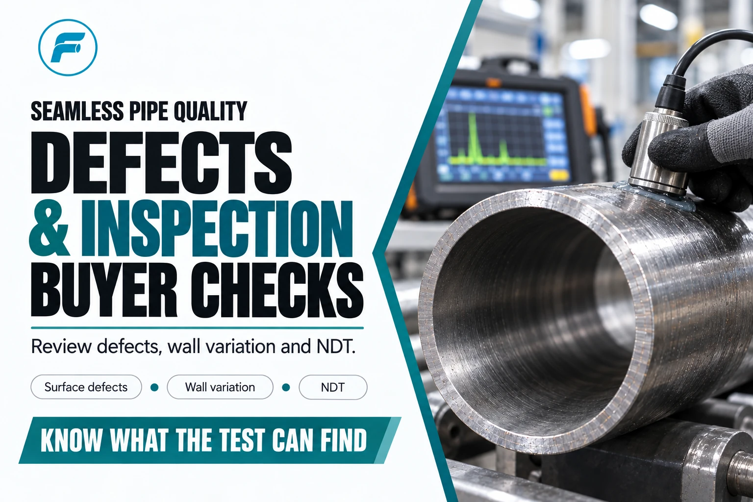
How should a boiler tube replacement be specified? Preserve failure evidence, identify the mechanism, confirm the current fluid and thermal conditions, match material and geometry to the tubesheet joint, and define testing and installation controls. Reordering the original grade and size without reviewing the failure can repeat the same leak mechanism.
This guide addresses replacement of seamless carbon and alloy steel tubes in boilers and related pressure parts. It is not a repair procedure and does not replace the ASME Boiler and Pressure Vessel Code, National Board Inspection Code, local jurisdiction, original equipment manufacturer instructions or the authorized repair organization’s quality system. Its purpose is to help owners, engineers, inspectors and buyers prepare a technically complete material and work package.
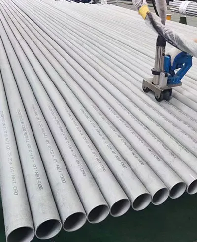
Boiler tubes are a specialized branch of the seamless steel pipe category. The seamless boiler tube page can be used to review available ASTM A192, A210 and A213 supply options, while the approved repair specification must control the final grade, wall basis, heat treatment and inspection scope.
Identify the boiler jurisdiction, registration, construction code and edition, repair organization, authorized inspector and owner-user requirements. Determine whether the work is a routine tube replacement, an alteration, a repair requiring an R stamp or another regulated activity. The classification affects design review, material acceptance, welding qualifications, inspection stages and final forms.
Collect the manufacturer’s data report, pressure-part drawings, material lists, weld details, previous repair reports, operating history and water-treatment records. Confirm design pressure, temperature, fluid side, tube location and intended service. The same nominal tube size may appear in economizer, waterwall, generating-bank, superheater or reheater service but face different metal temperatures and damage mechanisms.
Assign decision ownership. The boiler engineer approves design and material basis; the corrosion or reliability specialist evaluates damage; the authorized repair organization controls welding and quality records; the inspector confirms required hold points; purchasing obtains compliant material. A supplier can provide product information but should not approve a code substitution.
|
Decision |
Responsible technical input |
Required output before work |
|
Repair classification |
Jurisdiction, NBIC/code and inspector |
Approved repair route and forms |
|
Tube material |
Original records, design temperature and damage review |
Exact specification, grade and condition |
|
Replacement boundary |
NDE map, minimum wall and access |
Tube/section list and repair drawing |
|
Joining method |
Original design and qualified procedures |
Approved WPS and welder requirements |
|
Examination |
Code, repair plan and consequence |
ITP with acceptance criteria |
Common boiler-tube mechanisms include waterside corrosion, oxygen pitting, caustic attack, hydrogen damage, under-deposit corrosion, erosion, sootblower damage, fireside corrosion, fatigue, overheating, short-term overheat and long-term creep. Mechanical rubbing, poor circulation, flame impingement and weld defects may contribute. Each mechanism suggests different corrective actions.
Replacing a tube with thicker wall can extend life against uniform wastage, but it can also change heat transfer, tube metal temperature, flexibility and fit-up. Upgrading alloy may improve high-temperature strength but introduce welding, heat-treatment and material-mismatch issues. If overheating was caused by internal deposits or restricted flow, stronger metal alone does not restore cooling.
Use a cause-and-control register. For every proposed change, record the evidence it addresses and the verification method. Controls may include water-treatment correction, burner tuning, sootblower alignment, support repair, inspection interval, cleaning practice or operating limit in addition to replacement material.
|
Damage evidence |
Questions before replacement |
Controls beyond new tube |
|
Internal pitting/deposits |
Water chemistry, layup, oxygen ingress, circulation |
Treatment, cleaning, layup and monitoring |
|
Local external thinning |
Sootblower alignment, ash chemistry, gas velocity |
Shielding, alignment or operating correction |
|
Bulging/oxide growth |
Metal temperature, deposits, flow restriction |
Temperature/circulation correction and wider NDE |
|
Cracking near attachment |
Restraint, vibration, weld profile and thermal cycling |
Detail/support change and qualified welding |
|
Repeated failures in zone |
Population trend and common cause |
Expanded replacement boundary and inspection plan |
Start with the manufacturer’s data report and drawings, then reconcile prior repair records, material certificates, stamped or transferred markings and positive material identification. Portable PMI is valuable for alloy separation, but it may not identify carbon grade or heat-treatment condition reliably. Chemistry alone does not prove mechanical properties or code acceptance.
If original records conflict, treat material identity as unresolved. The repair engineer and inspector should define the testing and documentation needed to establish an acceptable basis. Do not choose a grade solely because dimensions match or because it has higher strength. Material substitution must account for allowable stress, temperature range, oxidation, weld procedure, post-weld heat treatment, thermal expansion and compatibility with headers or remaining tubes.
Maintain traceability from received tube to installed location. If full-length tubes are cut into panels or short sections, transfer heat identity using a controlled method. The as-built repair map should connect each installed piece to its MTC and weld records.
ASTM A192/A192M covers seamless carbon steel boiler tubes for high-pressure service. ASTM A210/A210M covers seamless medium-carbon steel boiler and superheater tubes. ASTM A213/A213M covers seamless ferritic and austenitic alloy-steel boiler, superheater and heat-exchanger tubes. These titles do not make the products interchangeable. The design and code material tables determine suitability.
State the exact product specification, grade and edition. Include the applicable ASME SA designation when required by the code documentation, and confirm edition alignment. For alloy tubes, include the full grade such as T11, T22 or T91 only when approved; do not use a P-grade pipe designation for tube material. Product form and grade nomenclature matter.
Review the site’s alloy steel pipe standards and grade selection guide for general orientation and the A335 P11, P22 and P91 comparison for pipe-grade context, but base the boiler-tube order on the tube specification and approved boiler design.
Boiler tube specifications can distinguish minimum-wall and average-wall orders. This is not wording trivia. An average-wall tube may have permitted local negative variation around nominal, while a minimum-wall product must not fall below the ordered minimum under the governing rules. The calculation, drawing and purchase order must use the same basis.
Record the required outside diameter, wall basis, ordered wall and permissible variation. If remaining tube is measured after years of service, do not use its current thinned wall as the original order size. Use design records, unworn samples and engineering calculation. A replacement section may need transition details if its wall or OD differs from existing material.
For bend locations, account for thinning on the extrados and thickening or wrinkling on the intrados. Specify minimum wall after bending, bend radius, ovality, flattening, tangent lengths and heat-treatment requirements. The straight-tube purchase wall may need additional allowance to achieve the required finished bend.
Use a qualified WPS appropriate to base materials, thickness, joint, process, position and heat treatment. Confirm welder or welding-operator qualification and consumable control. For dissimilar metal joints, engineering should approve filler selection, buttering, preheat, PWHT and examination.
Cleanliness and fit-up are fundamental. Remove oxides, oil and contaminants; protect the bore from foreign material. Record root gap, alignment and wall transition. Excessive internal reinforcement can disturb flow, while lack of penetration or undercut reduces integrity. Purging may be required for some alloys and processes.
Preheat, interpass temperature and PWHT must follow the approved procedure and code. Temperature measurement and recorder calibration should be documented. Heating bands and insulation must provide the required gradient. Hardness or replication may be required for high-temperature alloy repairs according to the engineering plan.
Visual examination should occur before, during and after welding. Surface methods such as magnetic particle testing for suitable ferromagnetic material or liquid penetrant testing for appropriate surfaces detect surface-breaking flaws. Radiography or ultrasonic examination addresses volumetric or planar flaws subject to geometry and procedure. Choose methods based on code and joint accessibility.
The National Board’s technical resources emphasize proper technique and surface preparation for magnetic particle examination. A method name alone is not a report. The procedure should state personnel qualification, equipment, calibration, coverage, timing relative to heat treatment and acceptance criteria.
For replacement tube population, use thickness mapping or other examination around the repair boundary. If damage is mechanism-driven, inspect beyond the visibly failed tube. Document locations in a stable coordinate system so future outages can compare the same zones.
|
Examination point |
Purpose |
Record |
|
Incoming tube |
Confirm identity, dimensions, surface and required mill NDE |
Receiving report and MTC reconciliation |
|
Formed bend |
Verify wall, ovality, surface and condition |
Bend inspection report |
|
Fit-up |
Confirm bevel, alignment, cleanliness and traceability |
Weld traveler |
|
Completed weld |
Detect surface/volumetric flaws as required |
NDE report linked to weld ID |
|
Pressure/leak test |
Demonstrate repair-system integrity under approved procedure |
Calibrated test chart and certificate |
|
Final closeout |
Verify marking, maps, forms and open-item closure |
Indexed repair dossier |
ASTM A106 is a seamless-pipe specification. If the purchaser has not fixed the manufacturing route, use the seamless versus ERW, LSAW and SSAW decision guide first; then use the ASTM A53, A106 and API 5L comparison to confirm the applicable product standard and approval boundary.
For international procurement, EN 10204 3.1 documentation is commonly specified; projects may require other validation. State the required certificate type before manufacture. The MTC should identify manufacturer, purchase order, specification and edition, grade, dimensions, wall basis, heat number, heat treatment, chemistry, mechanical results, required tests and authorization.
The repair dossier should connect more than the MTC. Include approved repair scope, material certificates, receiving inspection, transfer records, WPS/PQR and qualifications, consumable records, weld map, heat-treatment charts, NDE reports, pressure-test record, inspector releases, as-built drawing and jurisdictional forms. Index documents by tube or weld identifier.
Review certificate templates early. A missing heat-treatment field or ambiguous wall basis discovered after fabrication can delay release. Reconcile installed quantities and heat numbers against material issue records and remnants.
· Boiler tag, tube location, service and applicable code/jurisdiction.
· Approved repair classification and authorized organization interfaces.
· Failure mechanism summary and replacement boundary.
· ASTM/ASME tube specification, grade, edition and heat-treatment condition.
· OD, minimum/average wall basis, ordered wall, lengths and quantities/spares.
· Straight, bent, swaged or panel geometry with drawings and tolerances.
· Chemistry, mechanical properties, hardness and supplementary requirements.
· Mill NDE, dimensional inspection, marking and EN 10204 document type.
· Forming qualification, minimum wall after bend and post-form heat treatment.
· End preparation and compatibility with approved WPS.
· ITP, inspector notice, witness/hold points and dossier index.
· Packing, segregation, preservation and confirmed delivery milestones.
A boiler tube is not an interchangeable piece of metal defined by OD and wall alone. Its safe use depends on verified material identity, approved condition, geometry, forming history, joining process, examination and operating environment. The replacement package should show how every one of those elements connects to the code basis and the observed damage.
For available carbon and alloy standards, dimensions and production options, review the Forever Steel seamless boiler tube page, then submit the material requisition, drawing, repair ITP and required certificate format for technical review.
Codes and standards are copyrighted and editions change. Confirm the construction and repair editions, local jurisdiction and inspector requirements, and obtain licensed copies.
1. ASTM International,ASTM A192/A192M — Seamless Carbon Steel Boiler Tubes for High-Pressure Service, ASTM Standards catalog
2. ASTM International,ASTM A210/A210M-26 — Seamless Medium-Carbon Steel Boiler and Superheater Tubes
3. ASTM International,ASTM A213/A213M — Seamless Ferritic and Austenitic Alloy-Steel Boiler, Superheater and Heat-Exchanger Tubes
4. ASME,Required Code Books for ASME Certification
5. National Board,Magnetic Particle Examination technical article
6. BSI,BS EN 10204 — Metallic Products: Types of Inspection Documents
7. TWI,Complying with NACE Hardness Requirements
8. Electric Power Research Institute (EPRI),Failure Cause Analysis: Feedwater Heaters, report archived by the U.S. Department of Energy OSTI