+8615674993216
 sales@forever-steels.com
 English
 العربية


ASTM A213 vs A249 comes down to the permitted tube route and the equipment design. Match the route, dimensions and acceptance requirements before comparing offers.
· Choose A213 seamless tubing when the approved specification requires a seamless route.
· Consider A249 welded tubing when the design permits it and the grade, dimensions and final condition meet the requirements.
· Match the wall-thickness basis, tubesheet fit and inspection scope before comparing price or delivery.
For stainless steel heat exchanger tubes, confirm the permitted route and wall basis in the inquiry. The same grade and size description can conceal different acceptance requirements.
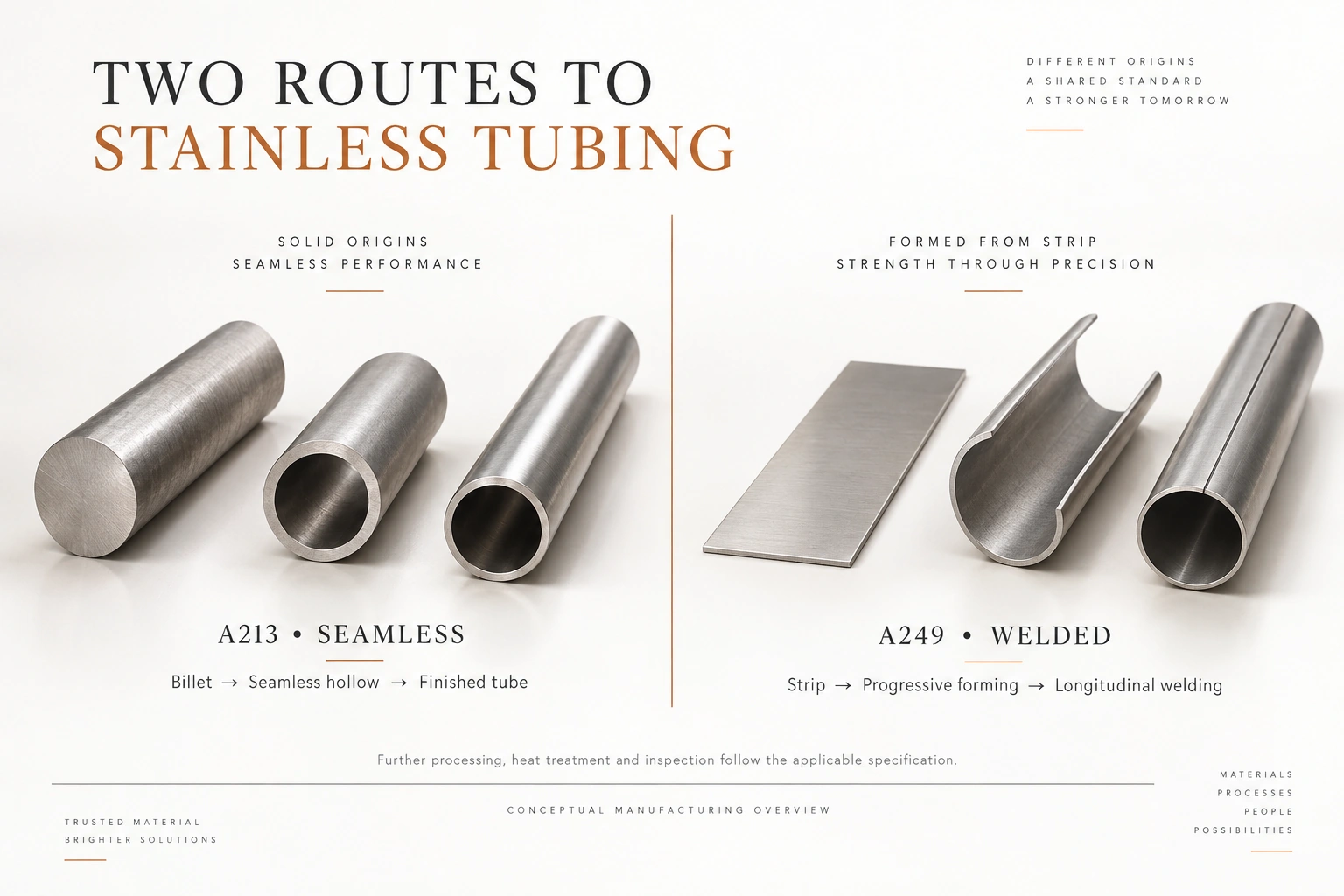
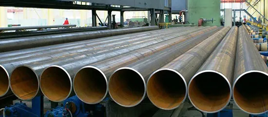
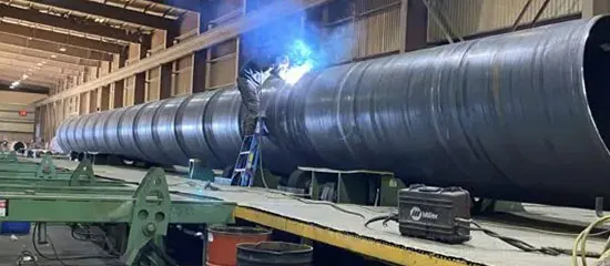
Figure 1. Simplified manufacturing routes. Select the route allowed by the equipment specification; the drawing does not establish pressure suitability.
|
Condition |
Route to consider |
What must be established |
|
Approved specification requires seamless tubing |
A213 |
A249 is a proposed substitution requiring technical approval |
|
Both routes are permitted for the service |
Compare A213 and A249 |
Match grade, dimensions, wall basis, delivery condition and testing |
|
Thick wall or an unusual diameter limits sourcing |
Route with a qualified, available manufacturing solution |
Obtain a size-specific offer; do not infer availability from the standard's scope |
|
Thin-wall bundle with tight fit requirements |
Either qualified route |
Compare actual OD, wall and ovality limits, including the weld region |
|
Lowest purchase cost is important |
Compare conforming offers |
Include testing, treatment, minimum order quantity and rejection risk |
|
Shutdown date controls the purchase |
Route with a confirmed delivery program |
Include material availability, production, inspection and document approval |
|
Chlorides, deposits or corrosion history are concerns |
Reassess the material and surface requirements first |
Seamless construction does not make an unsuitable grade corrosion-resistant |
Use the equipment code and design calculations to establish pressure suitability. Compare only routes permitted by the design. Pressure alone is insufficient to approve or reject welded tubing.
Seamless heat exchanger tubing has no longitudinal manufacturing weld. Welded heat exchanger tubing is formed from strip and joined along a longitudinal seam. A213 covers seamless ferritic and austenitic alloy-steel tubing, including stainless grades used in heat exchangers. A249 covers welded austenitic tubing, including heavily cold-worked welded tubing. A249 manufacture uses automatic welding without filler addition, followed by the required working and heat treatment.
The referenced editions are ASTM A213/A213M-25 and ASTM A249/A249M-24ae1. Use the edition specified by the equipment contract and obtain supply confirmation for the exact grade, OD, wall and length. A standard's usual scope range describes tube sizes; actual stock and manufacturing capacity require supplier confirmation.
|
Usual range stated in the scope |
A213 |
A249 |
|
Diameter endpoints |
3.2 mm inside diameter to 127 mm outside diameter |
3.2 mm inside diameter to 304.8 mm outside diameter |
|
Wall |
0.4–12.7 mm |
0.4–8.1 mm |
The lower diameter endpoint is ID, not OD. These are usual scope ranges, not absolute manufacturing limits. Common austenitic grades in both specifications include TP304, TP304L, TP316 and TP316L; check the exact grade and all applicable notes rather than assume every stainless alloy is included.
The distinction between seamless stainless steel pipe and welded stainless steel pipe is useful when discussing manufacturing routes, but a pipe specification must not replace the required heat exchanger tubing specification.
For an SA213 vs SA249 comparison, identify the required ASME edition and certification first. SA-213 and SA-249 address related tube routes, but the order must use the specification required by the equipment design.
A213 permits minimum-wall tubing and average-wall tubing when specified in the order. A249 uses nominal-wall thickness. These terms define the acceptance basis; they are not interchangeable labels for the same number.
Consider a drawing requiring 19.05 mm OD and at least 1.65 mm wall. Specify 1.65 mm as the minimum required thickness. If an offer states only “19.05 × 1.65 mm,” ask whether the wall is minimum, nominal or average and what negative tolerance applies.
For illustration, an offer of 1.65 mm nominal wall with an assumed 10% negative allowance would permit 1.485 mm. That is 0.165 mm below the drawing requirement. The 10% assumption demonstrates the ordering error; it is not a universal tolerance for both standards. Apply the contractual product standard, referenced general requirements and any agreed tighter limits.
Changing wall thickness affects more than the purchasing description. It changes the bore, the metal's conduction resistance and the dimensions available for the mechanical design. It does not change the outside heat-transfer area when OD, tube count and active length remain fixed.
|
Illustrative geometry |
1.65 mm wall |
1.85 mm wall |
|
Outside diameter |
19.05 mm |
19.05 mm |
|
Calculated inside diameter |
15.75 mm |
15.35 mm |
|
Internal flow area per tube |
194.8 mm² |
185.1 mm² |
|
Outside area for 100 straight tubes with 6 m active length each |
35.9 m² |
35.9 m² |
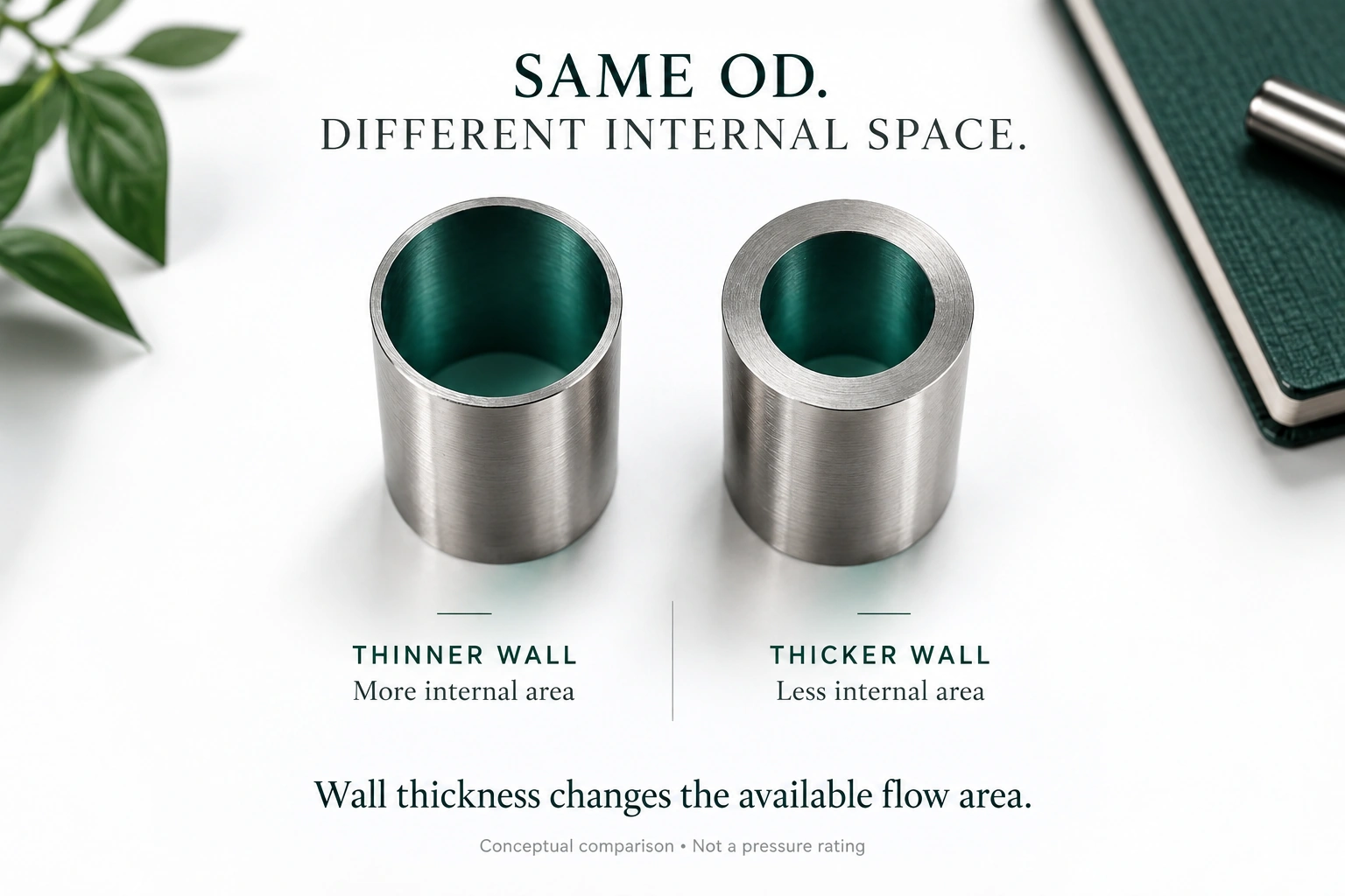
Figure 2. Conceptual comparison of wall thickness at the same OD. At the same outside diameter, a thicker wall reduces internal flow area. The illustration is not to scale or a pressure rating.
In this geometric example, the thicker tube has about 5.0% less internal flow area. At the same volumetric flow per tube, velocity would be about 5.3% higher. Pressure drop must be recalculated using the actual fluid, flow regime, roughness, length and fittings; it cannot be inferred from that percentage alone.
Use the relevant lower wall limit in the strength calculation. Determine the exchanger's pressure rating from the applicable design rules; the geometry example above only quantifies changes in bore and surface area.
Seamless tubing is formed without a longitudinal weld and can undergo hot or cold finishing. Cold finishing can help achieve the specified dimensions and condition, but “cold drawn” does not itself identify the final heat treatment. Check the delivered condition against the ordered stainless grade.
In welded tubing, strip forming, seam welding and subsequent processing affect the weld region and dimensions. A249 requires cold working before final heat treatment; its heavily cold-worked designation is a defined route, not a synonym for any welded tube with a smooth seam. The treatment record must relate to the delivered tube, not merely the starting strip.
For austenitic stainless grades, specify the required solution treatment and cooling, then review any later bending, welding or repair under the applicable procedure. Material suitability and fabrication quality still require their own checks.
Specify the required mechanical tests and tube-integrity tests in the inspection plan. Confirm specimen selection, lot definitions, dimensions and permitted alternatives against the ordered edition. Destructive tests must not be described as tests performed on every delivered tube.
|
Test |
A213 |
A249 |
Inspection-plan point |
|
Tension and hardness |
Required |
Required |
Identify grade limits, specimens and applicable lot |
|
Flattening |
Required |
Required |
Confirm sample selection and acceptance criteria |
|
Flaring |
Required |
Not the standard A249 flange test |
Do not treat flaring and flanging as the same test |
|
Flange test |
Not the standard A213 flaring test |
Required |
Review tube-end deformation and specimen requirements |
|
Reverse-bend |
Not a weld-seam test for seamless tubing |
Required where applicable |
Check the dimensional exceptions |
|
Reverse-flattening |
No longitudinal seam to assess |
Substitute under the specified reverse-bend exceptions |
Use the referenced A1016 procedure |
|
Hydrostatic or nondestructive electric test |
Each tube |
Each tube |
Identify the selected method and any additional order requirements |
A249's reverse-bend provision changes to reverse-flattening when the specified wall is at least 10% of OD, wall is at least 3.4 mm, or OD is below 9.5 mm. These are different procedures, not alternative names. Confirm unit-system values and applicability in the contractual edition before preparing test instructions.
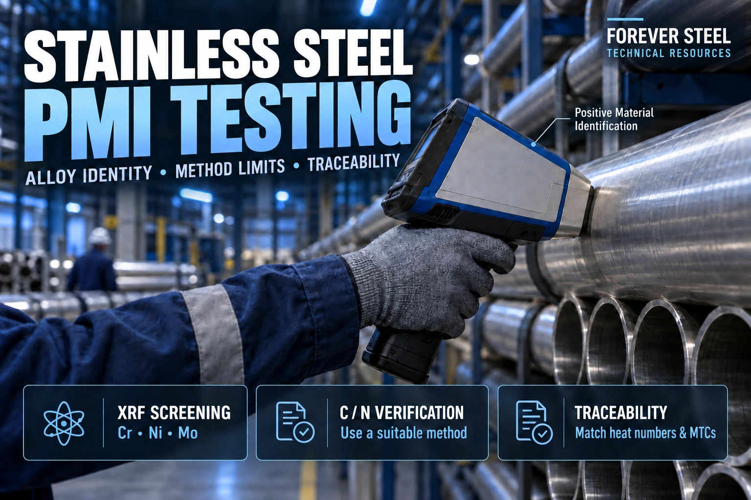
Additional ultrasonic inspection, corrosion testing or third-party witnessing must be identified separately when required. Require the NDT report to identify the examination technique, coverage and acceptance basis. For alloy checks, define the method and traceability using the stainless steel PMI testing guide.
For a replacement heat exchanger bundle, confirm the approved drawing, tubesheet-hole dimensions and joint procedure before ordering. Both tube routes can be considered for expanded or welded joints when the design and qualified procedures permit them.
For expansion, check OD and ovality against the tubesheet-hole requirements. Review the wall variation and tube-end condition that the expansion procedure must accommodate. For welded tubing, include the weld region in that review: a seam with an unacceptable profile or unqualified condition is a problem even if the average tube dimension is correct.
For tube-to-tubesheet welding, confirm the end preparation, material combination and joint detail. If the design uses both expansion and welding, settle their sequence and qualification requirements before ordering. Do not use a worn tube's remaining wall as the sole specification for a replacement bundle; reconcile it with the approved drawing and repair scope.
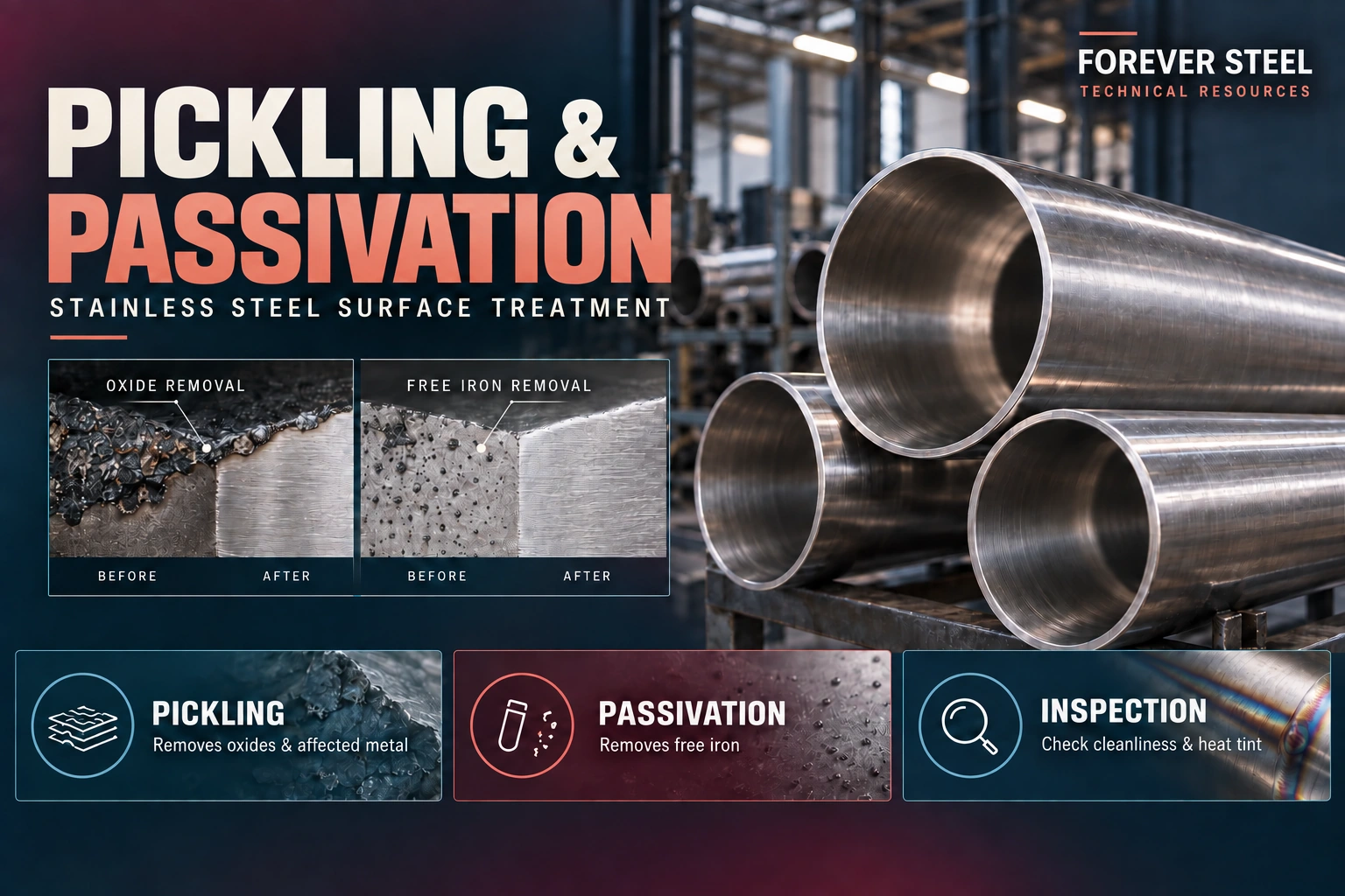
Select the alloy and surface condition for the fluid, temperature and corrosion history. Review thermal history, residual stress, deposits and weld condition alongside the manufacturing route. For heat tint or handling contamination, define treatment and acceptance using the stainless steel pipe pickling and passivation guide.
Conventional 304L and 316L materials can suffer chloride-related localized corrosion or stress corrosion cracking under relevant conditions. Alleima's duplex tube data discusses the chloride stress-corrosion limitations of these conventional austenitic grades. This supports reviewing the alloy when service history is unfavorable, rather than assuming a route change alone will solve the failure.
Review solution treatment, final surface acceptance and service-specific alloy suitability as separate requirements. Each addresses a different part of corrosion performance.
Include the equipment, material, dimensional and inspection requirements in the inquiry. Attach the drawing when tubesheet fit, end preparation or U-bend geometry controls the purchase.
|
Inquiry field |
Information to provide |
|
Equipment and design basis |
Equipment reference, code or project specification, drawing revision |
|
Material |
Product standard and edition, grade or UNS designation, permitted route |
|
Dimensions |
OD, wall value and minimum or average or nominal basis, required tolerances |
|
Length and quantity |
Active and overall length as applicable, number of tubes, spare quantity |
|
Tube connection |
Expanded, welded or combined joint; required end preparation |
|
U-bend requirements |
Bend drawing, radii, leg lengths and any bend-specific treatment or inspection |
|
Final condition |
Required heat treatment and internal and external surface condition |
|
Inspection |
Hydrostatic or electric method, additional NDE, PMI method and coverage if required |
|
Documents |
MTC or inspection-certificate type, traceability, test reports and endorsement requirements |
|
Delivery |
Required date, packaging, inspection hold points and proposed deviations |
Planning a replacement bundle? Send your tube inquiry to Forever Steel with the drawing, grade, OD, wall basis, length, quantity and inspection requirements. Ask for a quotation that states the proposed route and identifies any deviation from the equipment specification.
Only when the equipment specification and responsible technical authority permit the substitution. Match the dimensional, material, manufacturing and inspection requirements before approving it.
No universal route rule replaces the equipment code and design calculation. The approved specification, dimensions, material condition and examination requirements govern the selection.
No. It changes bore and thermal resistance and can affect tube-side velocity and pressure drop. Strength, thermal duty and hydraulic performance must be checked together.
No. The grade must still suit the service, and the final surface and fabrication condition must meet the specification.