+8615674993216
 sales@forever-steels.com
 English
 العربية

Girth-weld fit-up depends on pipe-end geometry as a system: end ovality, hi-lo, wall-thickness distribution, bevel condition, end squareness, matching and handling history. Average outside diameter alone cannot establish fit-up readiness.
A diameter-tape reading gives average size. It does not show where the end is high or low. For critical girth welding, we record local diameter and wall thickness at fixed clock positions. The weld seam is used as the orientation reference, and both ends are identified separately. If an end is re-cut or re-bevelled, the old map is no longer valid.
|
Measurement |
Why it matters at site |
|
Average end OD |
Confirms general clamp and size compatibility |
|
Local diameter by clock position |
Shows the actual ovality pattern |
|
Wall thickness by clock position |
Predicts internal mismatch |
|
Bevel angle and root face |
Controls root opening and penetration |
|
End squareness |
Prevents root gap changing around the circumference |
|
Seam reinforcement |
Affects internal clamp clearance and local transition |
Mechanical expansion improves roundness, but it does not correct every forming or welding variation. The inspection point must also be defined. A measurement taken too far from the bevel may not represent the interface used for welding. On demanding orders, we agree the distance from the end, the number of readings, instrument type and ovality calculation before production.
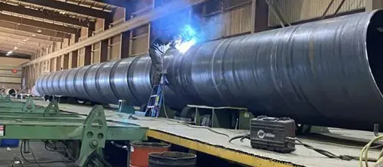
The longitudinal seam requires separate attention. The field girth weld crosses the seam at one position, where internal reinforcement, external reinforcement and the transition into base metal affect clamp clearance and local alignment. Grinding may be allowed within defined limits, but it must not reduce the remaining wall below the requirement. Any repair or grinding in the end area should be followed by the specified NDT and a new dimensional record.
Bevel condition also changes fit-up. A nominal bevel angle does not define root face, end squareness, internal transition or surface finish. If the cut is not square to the pipe axis, the root gap changes around the circumference even when both ends are round. For heavy-wall pipe, we measure bevel and root face at several positions and record re-bevelled ends separately.
Wall distribution is as important as ovality. External clamps align outside surfaces; internal clamps align the bore. A high-wall sector meeting a low-wall sector can create internal offset even when the OD looks acceptable. The project should state whether the limit applies to internal mismatch, external mismatch or both.
End matching is useful when installation productivity justifies the additional control. We first reject any nonconforming end. Accepted ends can then be grouped by average diameter and wall band, or matched using orientation-aware measurement maps. Designated pairs must remain identifiable through storage, loading and field stringing. A matching exercise has little value if the pipes are randomly unloaded and rotated.
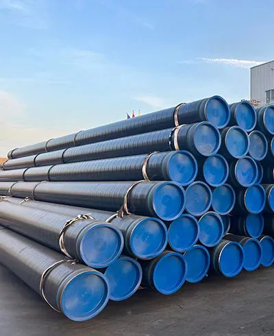
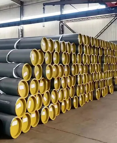
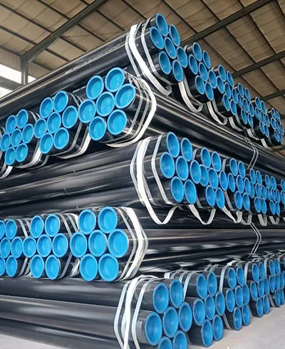
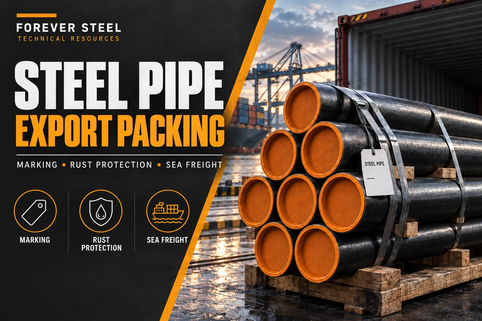
Transport is a frequent source of avoidable end damage. Hooks on bevels, narrow dunnage, excessive stack height and lashing through unsupported ends can change a pipe that passed final inspection. For large OD or relatively thin wall, the packing plan may require end rings or internal bracing. Non-metallic slings and shaped supports should be specified rather than assumed.
|
Factory control |
Field control |
|
End A/B marking and seam orientation |
Preserve identity during unloading |
|
Clock-position OD and wall map |
Recheck suspect ends at the same positions |
|
Bevel and squareness report |
Inspect for handling damage before fit-up |
|
Matching list and loading sequence |
Maintain the intended installation order |
|
Packing photographs |
Compare condition after arrival |
When excessive hi-lo is found, we record the two pipe numbers, end designations, orientation, clamp type and actual readings before any correction. Rotation or substitution may solve the mismatch. Heating, local pressing, grinding or counterboring requires engineering approval and reinspection; these are not routine site adjustments.
The investigation should first confirm that the correct matched ends and orientation were used. It should then separate manufacturing geometry from transport deformation and field handling. Comparing the factory end map with the arrival measurements is much more useful than arguing from photographs alone. If the same ovality direction appears in the factory record, the cause is probably upstream; if the profile changes after shipment, support and lashing should be reviewed.
For matched-pipe programmes, loading sequence is part of quality control. Pipe numbers and End A/End B designations should appear on the loading list, and the site needs a replacement rule when a pipe is damaged or removed from the planned string. Without that control, a detailed matching calculation is reduced to paperwork.
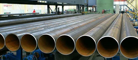
For LSAW steel pipe used with automatic girth welding or tight tie-in tolerances, pipe-end measurement and transport protection should be written into the purchase specification. A single line saying “OD tolerance according to API 5L” does not define the local geometry needed by the welding spread.
Nominal OD alone cannot predict girth-weld fit-up. The purchase specification should define the measurement method, distance from the end, orientation, frequency and acceptance criteria for the characteristics that matter to field alignment.
| Characteristic | Record | Fit-up effect |
| End circumference/diameter | Measured value and method | Matching between adjacent pipes |
| Ovality | Maximum/minimum axes and end position | Radial mismatch and clamp effort |
| Squareness | End-face deviation | Root gap consistency |
| Wall/hi-lo | End-wall readings and matching rule | Internal mismatch at the girth weld |
For project LSAW pipe, Forever Steel can include an agreed end-measurement schedule and pipe-number traceability in the pre-shipment dossier. End matching supplements, but does not replace, field fit-up procedure and welding acceptance controls.
· LSAW Steel Pipe Product Specifications and Supply Range
· UOE vs JCOE: Which LSAW Forming Route Fits Your Project?
· LSAW Pipe Nonconformance: How We Contain, Repair and Close the Record
· Pipe Beveling Guide: Bevel Angle, Root Face and Weld Preparation
Confirm the ordered edition and applicable test or acceptance requirements against the project specification.